Energy storable air conditioning device

a technology of energy storage and air conditioning device, which is applied in the direction of electrical apparatus casing/cabinet/drawer, domestic cooling apparatus, instruments, etc., can solve the problems of reducing the cooling or heating ability, the number of fans and energy storage units, and the efficiency of air conditioning devices, etc., to achieve excellent regulation efficiency and facilitate expansion and replacement of fans

Inactive Publication Date: 2015-02-17
KUNSHAN JUZHONG ELECTRONICS
View PDF7 Cites 6 Cited by
  • Summary
  • Abstract
  • Description
  • Claims
  • Application Information

AI Technical Summary

Benefits of technology

[0007]The object of the invention is to provide an energy storable air conditioning device including modularized fan and energy storage unit, which facilitates expansion and replacement of fan and energy storage unit so as to obtain excellent regulation efficiency.
[0010]As the energy storage unit is modularized, it is convenient to replace the failed energy storage unit so as to recover cooling or heating ability of the energy storable air conditioning device to maintain excellent efficiency.
[0011]In addition, because phase change material has large heat storage capacity, it is maintained at melting point for a long time to absorb heat or release heat for cooling or heating so as to save energy.
[0012]Furthermore, the energy storable air conditioning device of the invention includes an air intake module filtering air flow at the air inlet to provide better air quality. In addition, the energy storable air conditioning device of the invention further includes a seat which supports a main body (or a third main body) and has a distance from ground to facilitate air flowing into the seat through the air inlet. The energy storable air conditioning device of the invention further includes a cover, and an air guide slot is formed on the cover to guide hot or cool air flow to a desired position to lift efficiency of the air conditioning device.
[0013]In addition, the air blower and energy storage unit is modularized to facilitate expansion or replacement. The number of air blower module and energy storage module can be increased or decreased depending on requirement. The positions of the air blower module and energy storage module can also be adjusted for easy operation of the air conditioning device.

Problems solved by technology

To supply cool air or warm air for temperature regulation, the air conditioning devices may consume large electrical energy.
However, since the positions of the fan and the energy storage unit are fixed, the fan and the energy storage unit cannot be moved to change the configuration arbitrarily, and the number of the fan and the energy storage unit, which related to the efficiency of the air conditioning device, cannot be changed either.
In addition, when some of the energy storage unit fails, which cause reduction of the cooling or heating ability, it is inconvenient to replace them.

Method used


Image

  • Energy storable air conditioning device
  • Energy storable air conditioning device
  • Energy storable air conditioning device

Examples


second embodiment

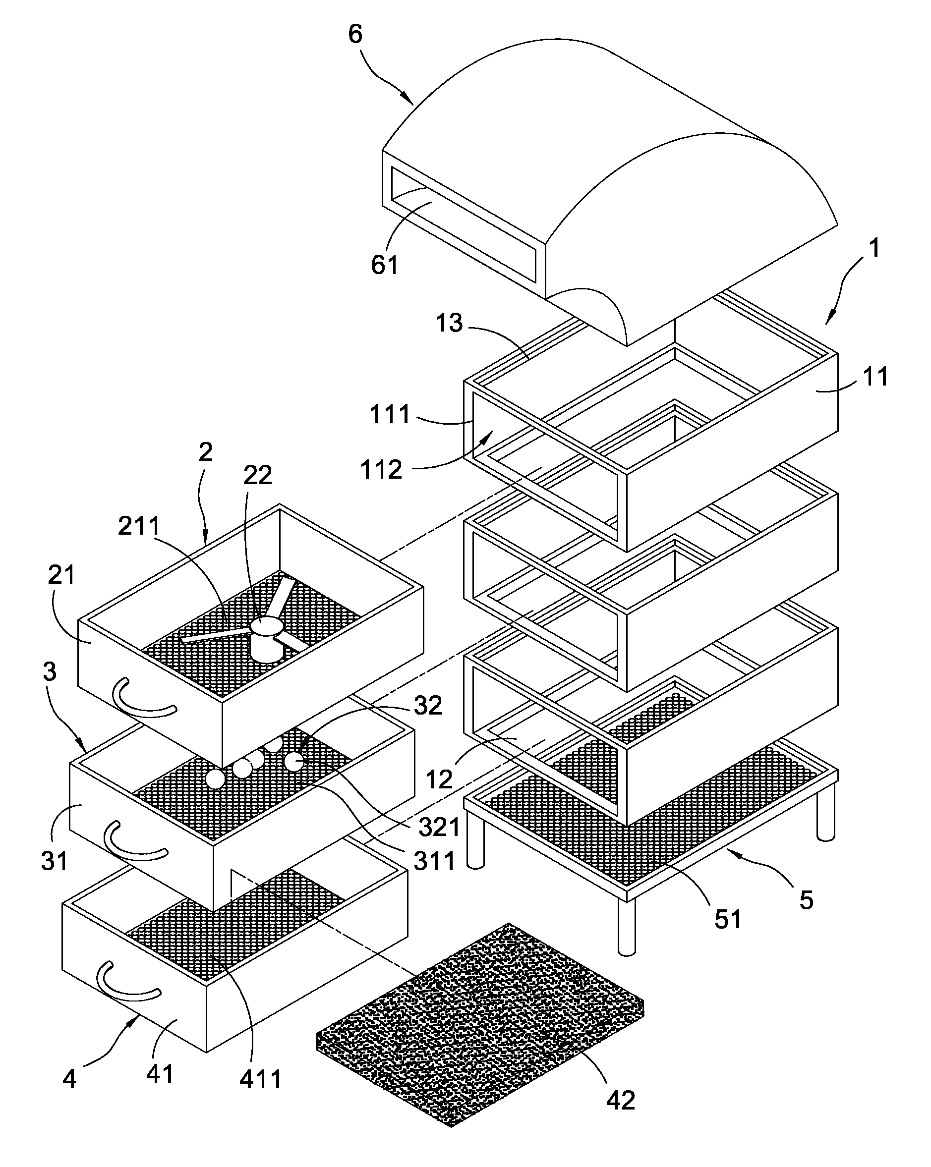
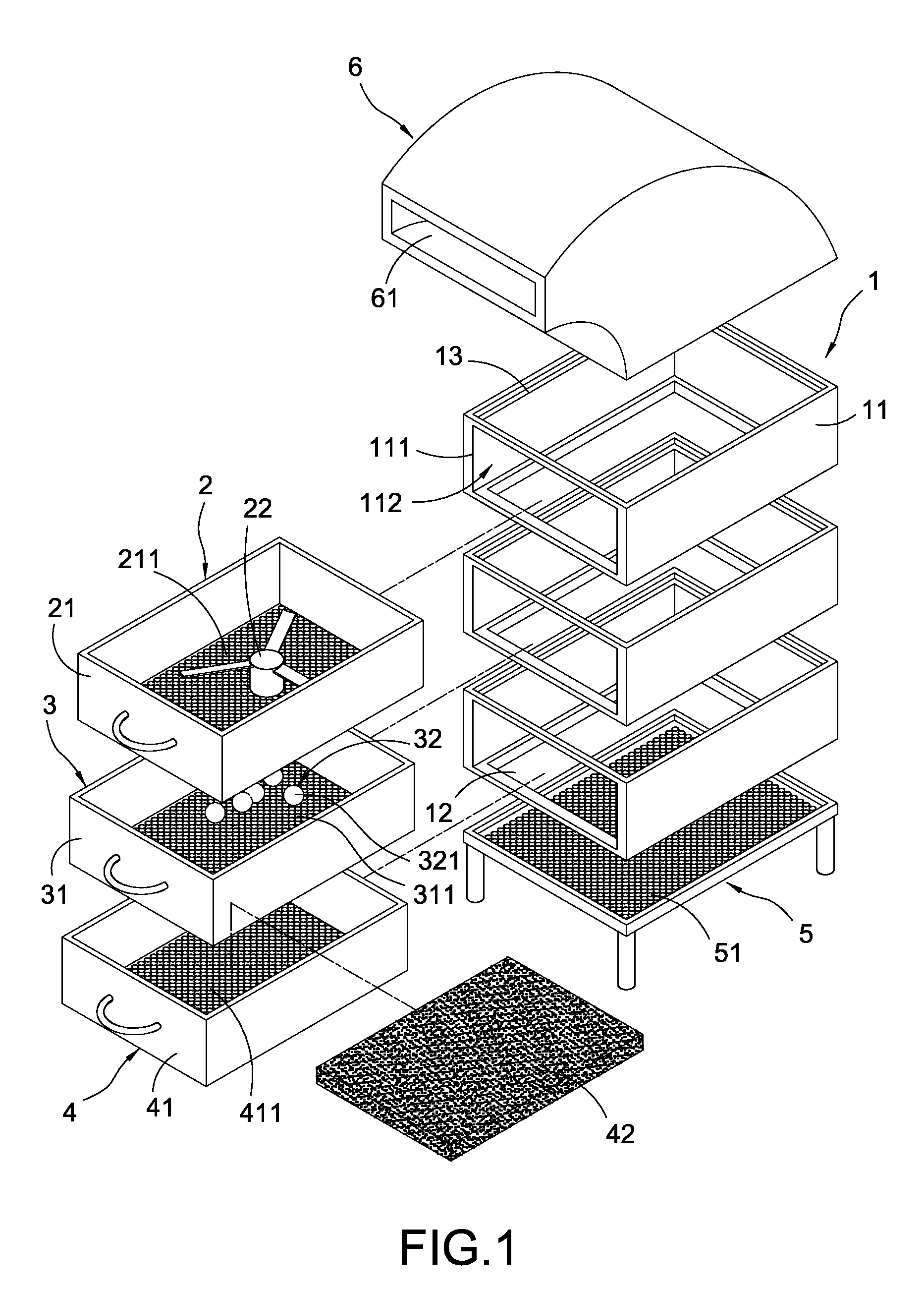
[0037]the invention is depicted in FIG. 6. The main body 1 includes a frame 11. The frame 11 has several longitudinally disposed openings 111 and each opening 111 corresponds to one of the receiving spaces 112. Since top and bottom of each frame 11 are opened, when the frames 11 are stacked, the opened top side and bottom side of the stacked structure of the frames 11 serve as the air outlet 13 and air inlet 12 respectively.

[0038]FIGS. 7 and 8 depict the third and fourth embodiments of the invention. Each air blower module 2 includes a first main body 21′ and a fan 22′ disposed in the first main body 21′. The top of the first main body 21′ is an opening, and the bottom of the first main body 21′ has a meshed or porous structure 211.

[0039]Each energy storage module 3 includes a second main body 31′ and an energy storage unit 32′ disposed in the second main body 31′. The top of the second main body 31′ is an opening and the bottom of the first main body 21′ has a meshed or porous stru...

fifth embodiment

[0045]The fifth embodiment is described as follows. The main body 1 includes several frames 11 stacked horizontally (side by side). Each frame 11 has an opening 111 corresponding to one of the receiving spaces 112. The air inlet 12 and air outlet 13 are formed on left side and right side of the main body 1. Each frame 11 has several feet or wheels to support the frames 11 and keep away from the ground for a distance. The wheels facilitate movement, replacement and attachment of the frames 11.

sixth embodiment

[0046]The sixth embodiment is described as follows. The main body 1 includes a frame 11 provided with openings 111 corresponding to the receiving space 112. The air inlet 12 and air outlet 13 are formed on left side and right side of the frame 11. The frame 11 has several feet or wheels to support the frames 11 and keep away from the ground for a distance. The air conditioning device is easily moved by the wheels.

[0047]The first drawer 21 has the meshed or porous structure 211, and the second drawer 31 has the meshed or porous structure 311 corresponding to the meshed or porous structure 211. In the fifth and sixth embodiments, the meshed or porous structure 211 is formed on the two opposite sides of the first drawer 21, and the meshed or porous structure 311 is formed on the two opposite sides of the first drawer 31. The first drawer 21 is connected to the second drawer 31.


PUM


Abstract

An energy storable air conditioning device includes a main body, at least one air blower module and at least one energy storage module. The main body has an air inlet, an air outlet and several receiving spaces connected to each other and disposed between the air inlet and the air outlet. The air blower module includes a first drawer inserted into one of the receiving spaces and a fan disposed in the first drawer. The energy storage module includes a second drawer inserted into another one of the receiving spaces and an energy storage unit disposed in the second drawer. The first drawer is connected to the second drawer.

Description

BACKGROUND OF THE INVENTION[0001]1. Field of the Invention[0002]The invention is related to an energy storable device, and in particularly related to an energy storable air conditioning device.[0003]2. Description of the Related Art[0004]Air conditioning devices are often used to reduce indoor temperature in the day time or in summer or used to reduce temperature of a refrigerator. They are also used to raise indoor temperature at night or in winter or used to raise temperature of a dryer. To supply cool air or warm air for temperature regulation, the air conditioning devices may consume large electrical energy.[0005]Since the air conditioning devices consumes large energy and the refrigerant used in the air conditioning devices may pollute environment, an energy storable air conditioning device is desired. Such an energy storable air conditioning device may include a seat and an energy storage unit. The seat has a first air entrance and a second air entrance, and a first fan and a ...

Claims


Application Information

Patent Timeline
Patent Type & Authority Patents(United States)
IPC IPC(8): F25D17/04
CPCF24F5/0017Y02E60/14
Inventor KUO, DAH-CHYIWANG, XUE-HAILONG, LING
Owner KUNSHAN JUZHONG ELECTRONICS
Why Eureka
Try Eureka