Retractable separating systems and methods

a technology of separating system and lead, applied in the field of system and method, can solve the problems of scar tissue or adhesion development, metal sheaths that are currently used to strip scar tissue from implanted leads often cannot traverse the tortuous lead path, and the metal sheaths that are currently used to strip scar tissue from implanted leads may present complications, so as to minimize the force on the lead and the vascular system, and the effect of safely deployed within the vascular system of the patien

Active Publication Date: 2015-02-24
SPECTRANETICS
View PDF678 Cites 43 Cited by
  • Summary
  • Abstract
  • Description
  • Claims
  • Application Information

AI Technical Summary

Benefits of technology

[0006]Advantageously, embodiments of the present invention encompass cutting, stripping, and dilating device having designs unique in their simplicity. An exemplary separating system involves a minimum number of parts, for example a retractable assembly and an inexpensive low profile flexible sheath that easily tracks over a pacing lead. Mechanical sheath and retractable assembly embodiments can be safely deployed within the vascular system of a patient. For example, a torqueable and flexible polymer sheath can be coupled with a 2-piece tip section that houses a cutting, stripping, or dilating element. The element can be deployed or exposed to separate tissue by rotating the sheath in one direction. Conversely, the element can be retracted back into the tip by rotating the sheath in the other direction. The penetration action of the sheath can be accomplished by rotation of the sheath to minimize force on the lead and vascular system.

Problems solved by technology

A common problem associated with pacing leads is the development of scar tissue or adhesions where the pacing lead contacts the patient's body tissue.
Patient tissue can become attached with the pacing lead, and thus removal or extraction of the pacing lead may present complications.
Unfortunately, metal sheaths that are currently used to strip scar tissue from implanted leads often cannot traverse the tortuous lead path, and in many instances can only be used in proximal locations.
Currently used plastic sheaths may be able to access certain distal lead locations, but often suffer from poor torque properties, low radiopacity, and ineffective penetration into hard tissue because they have soft tips that deform when in contact with the hard tissue.
However, longitudinal forces can be easily lost during the procedure by tortuousity or curvature in the lead and by friction encountered within the anatomy or over the pacing lead.
Longitudinal forces also may require heavy counter traction on the lead-that can result in pacing lead breakage.
At least some of these devices, however, involve complicated activation mechanisms and may not be well suited for negotiating the tortuous paths present in certain vascular or physiological environments.
Although effective in some circumstances for removing chronic implanted pacing leads, many laser systems can be expensive and unaffordable to many treatment centers.

Method used


Image

  • Retractable separating systems and methods
  • Retractable separating systems and methods
  • Retractable separating systems and methods

Examples


Embodiment Construction

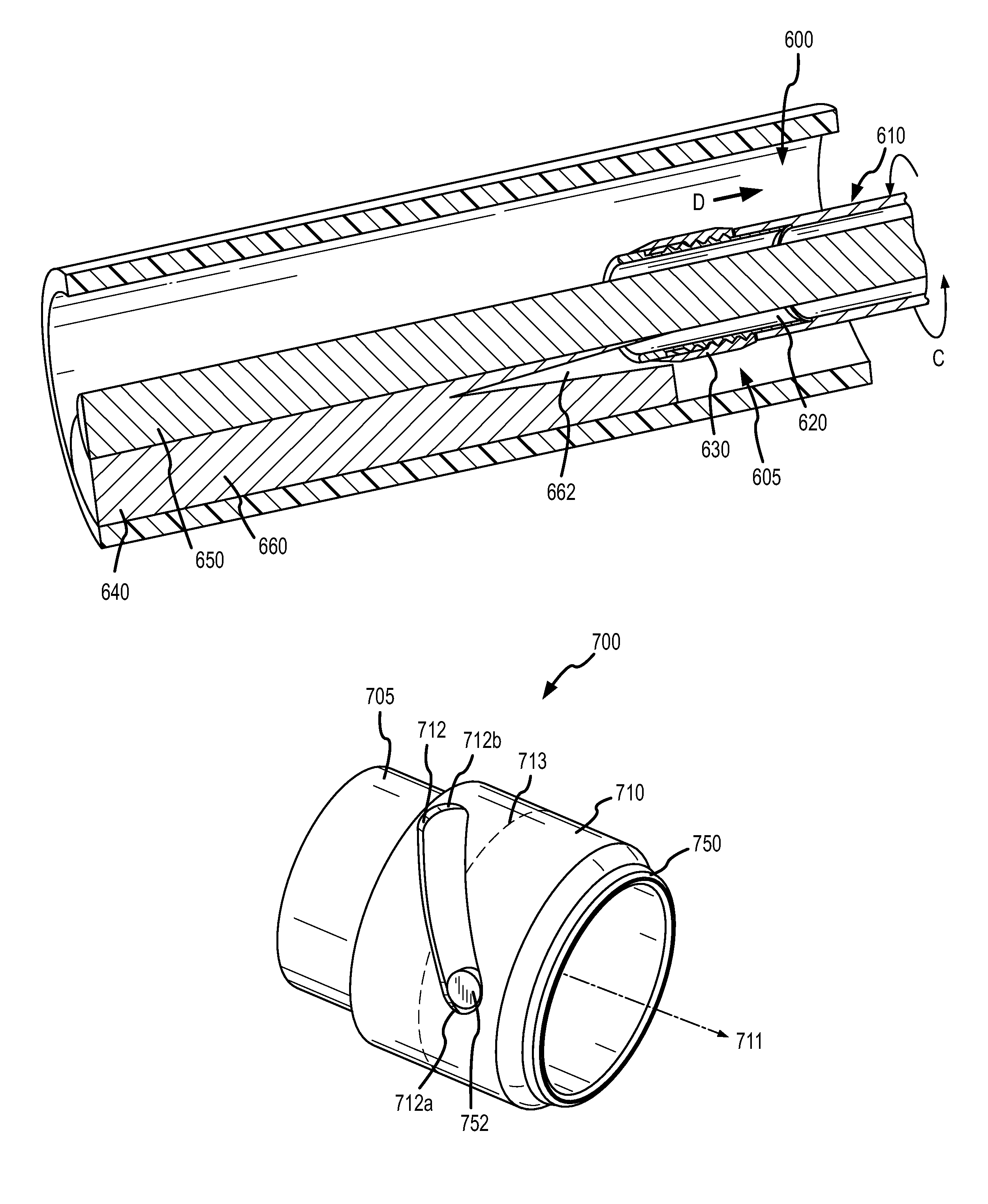
[0023]Embodiments of the present invention provide a mechanical sheath and separating tip that can be safely deployed within the vascular system of a patient. A separating system can include, for example, a flexible sheath coupled with a separating assembly, which includes a separator and a tip. The separator can be advanced distally beyond the tip by rotating the sheath in one direction. Conversely, the separator can be retracted back into the tip by rotating the sheath in the other direction. The penetration action of the sheath can be accomplished by rotation of the sheath to minimize force on the lead and vascular system.

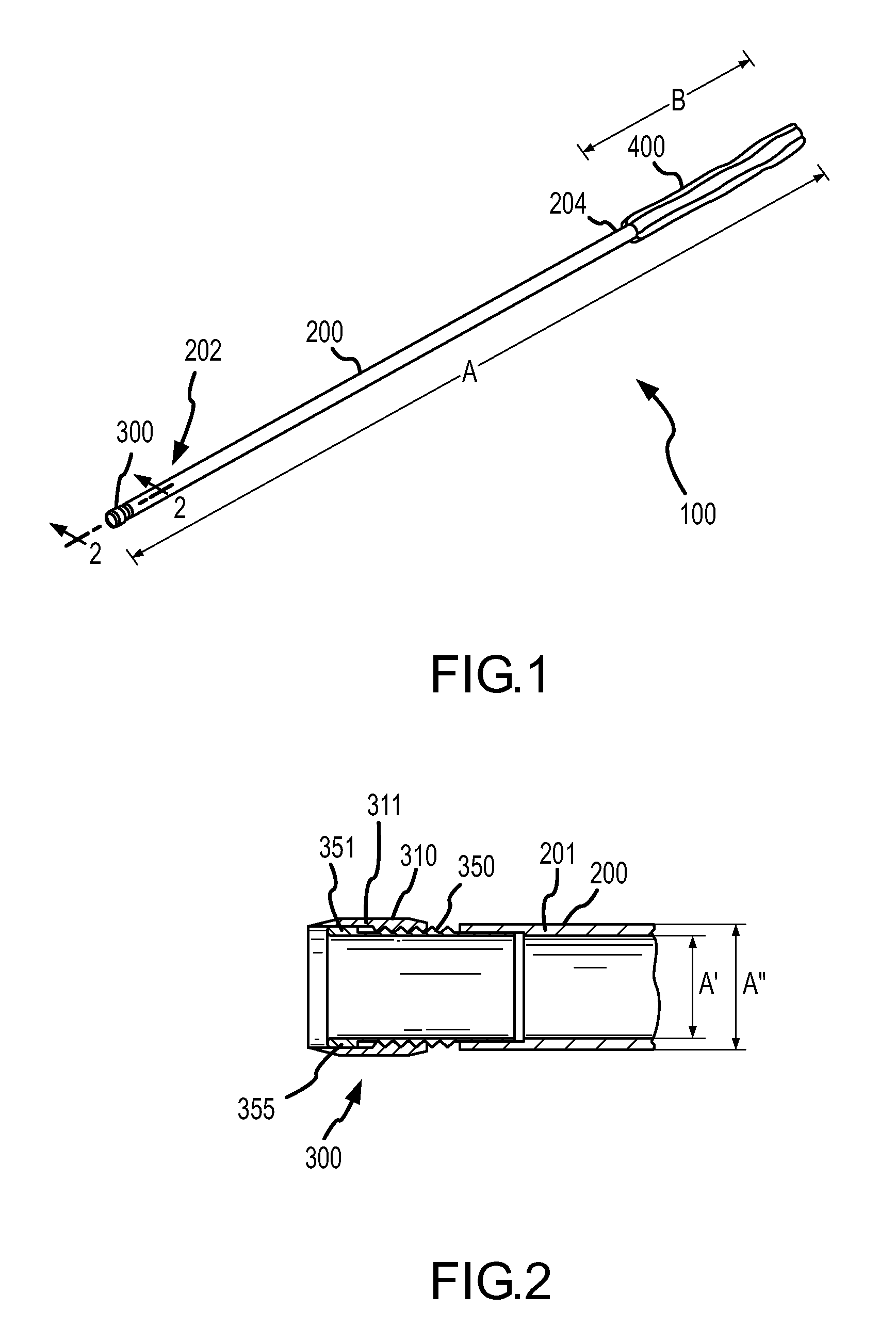
[0024]Turning now to the drawings, FIG. 1 shows a separating system or tool 100 according to one embodiment of the present invention. Separating or cutting system 100 includes a sheath 200, a separating assembly 300, and a handle 400. In some embodiments, sheath 200 includes or is manufactured from a flexible polymer such as Pebax® or Teflon®, and may also inclu...


PUM


Abstract

A method for detaching an object from a patient includes providing a tool having a sheath, and a separating assembly operably coupled to a distal end of the sheath. The separating assembly includes a separator moveably coupled to a tip via a threadable connection. The separating assembly is placed near patient tissue that is attached to the object, the sheath is rotated to move the separator distal to the tip, and the separator is applied to the patient tissue that is attached to the object, so as to separate the tissue. A separating system includes a sheath, and a separator threadably coupled with a distal end of the sheath. The separator is adapted to switch between a first configuration where a separating means is deployed, and a second configuration where the separating means is undeployed.

Description

CROSS-REFERENCES TO RELATED APPLICATIONS[0001]This application is related to U.S. patent application Ser. No. 11 / 615,005, filed Dec. 22, 2006 (titled Tissue Separating Systems and Methods) the entire contents of which are incorporated herein by reference for all purposes.BACKGROUND OF THE INVENTION[0002]The present application relates generally to systems and methods for separating an object from tissue in a patient, and more specifically, to techniques for removing pacing leads from a patient.[0003]Cardiac pacing systems typically include a pacemaker and a pacing lead, which are placed inside the body of a patient. The pacemaker includes a power source and circuitry configured to send timed electrical pulses to the pacing lead. The pacing lead carries the electrical pulse to the heart to initiate a heartbeat, and transmits information about the heart's electrical activity to the pacemaker. The pacing lead can include a fixation mechanism that holds the lead to the cardiac tissue. I...

Claims


Application Information

Patent Timeline
Patent Type & Authority Patents(United States)
IPC IPC(8): A61B17/00A61B17/32A61B17/3205A61B17/3207A61B19/00A61N1/05
CPCA61B17/320758A61B17/32053A61B19/54A61B2017/00336A61B2017/320024A61B2017/320741A61B2019/4857A61N2001/0578A61B90/39A61B2090/0811A61B17/320016A61N1/056
Inventor TAYLOR, KEVIN D.
Owner SPECTRANETICS
Why Eureka
Try Eureka