
Backlight unit and liquid crystal display device

a liquid crystal display device and backlight technology, applied in the direction of illuminated signs, display means, instruments, etc., can solve the problems of preventing the proceeding of the led light, and the fixation portion cannot be easily achieved, so as to achieve sufficient distance and sufficient distance

Active Publication Date: 2015-02-24
PANASONIC INTELLECTUAL PROPERTY CORP OF AMERICA
View PDF8 Cites 0 Cited by
  • Summary
  • Abstract
  • Description
  • Claims
  • Application Information

AI Technical Summary

Benefits of technology

[0009]The present invention has been conceived in view of the above, and aims to provide a backlight unit and a liquid crystal display device capable of ensuring freedom in wiring around the light source, and preventing the pillar from hindering the proceeding of the light.
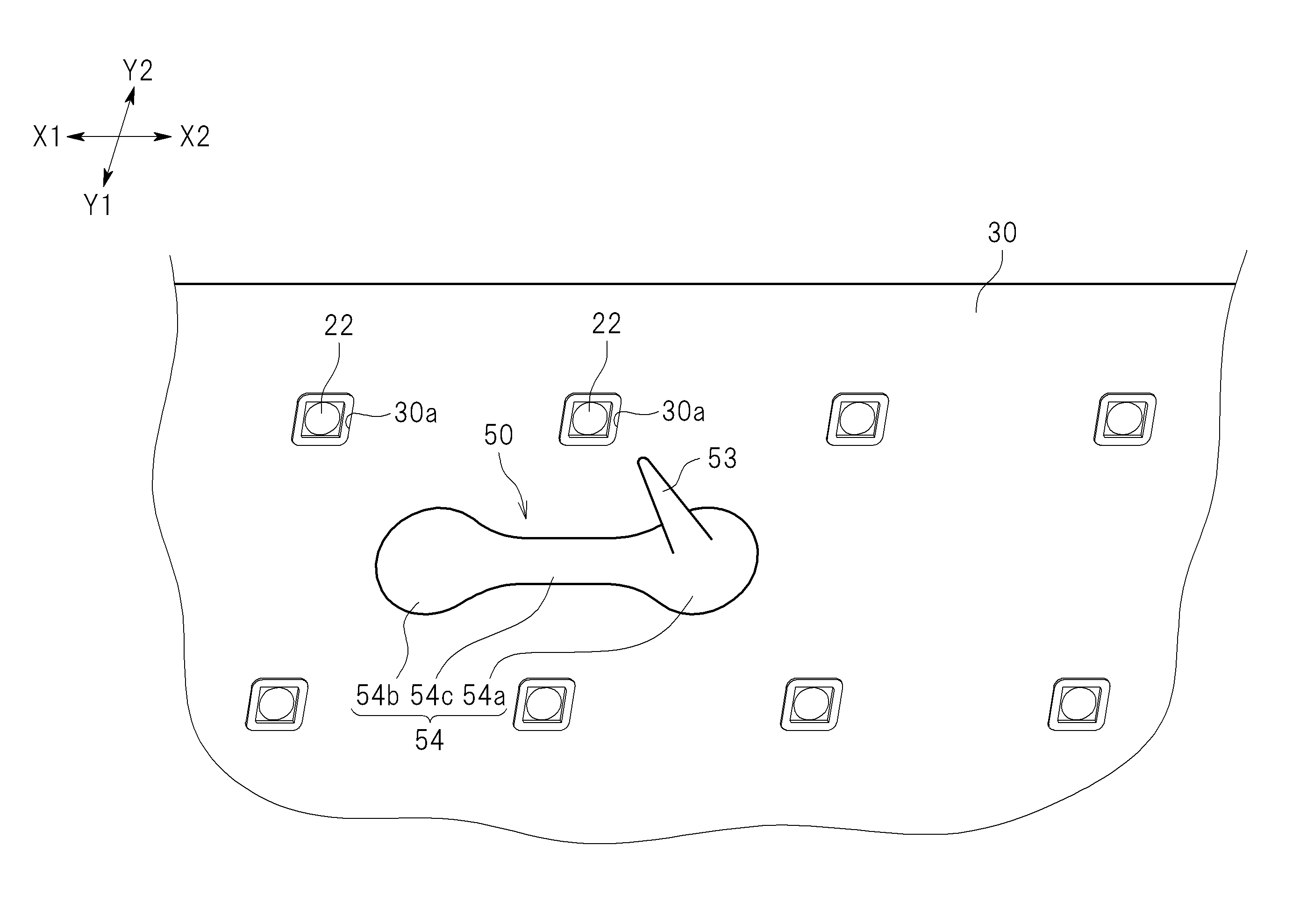
[0012]According to the present invention, the pillar is formed being aligned to the first fixation portion in a direction perpendicular to the substrate. Therefore, when a hole for accepting the first fixation portion is formed at a position apart from the respective light sources so that the first fixation portion is positioned apart from the respective light sources, the pillar as well is positioned apart from the respective light sources. This makes it possible to increase freedom in wiring around the light source and to prevent the pillar from hindering the proceeding of the light from the light source.
[0013]In one embodiment of the present invention, the first fixation portion may be surrounded by a plurality of light sources forming one unit of the matrix. In this embodiment, sufficient distance can be ensured between the first fixation portion and the light sources around the first fixation portion, which can increase freedom in wiring around the light source.
[0015]In this embodiment, the second fixation portion may be positioned outside the plurality of light sources surrounding the first fixation portion. With the above, a sufficient distance can be ensured also between the second fixation portion and the light sources. Further, in this embodiment, the second fixation portion may be positioned opposite the first fixation portion across a straight line, the straight line passing through two of the plurality of light sources surrounding the first fixation portion. With the above, a more sufficient distance can be ensured between the second fixation portion and the light source around the second fixation portion. Further, in this embodiment, the support pin may include a coupling portion positioned on the front side of the substrate, for coupling the first fixation portion and the second fixation portion. Further, the coupling portion may include a first connected portion to which the first fixation portion is connected; a second connected portion to which the second fixation portion is connected; and an extending portion extending between the first connected portion and the second connected portion. Further, the width of the extending portion is smaller than the width of the first connected portion and the width of the second connected portion. With the above, it is possible to prevent the coupling portion from hindering the light from the proceeding of the light source.

Problems solved by technology

However, the support pin disclosed in Japan Patent Publication No. 2009-104978 may cause a problem such as is described below when used in the above mentioned direct type backlight unit.
In addition, if the pillar supporting the diffusing panel is positioned close to the LED's, the pillar may hinder the proceeding of the light from the LED's.
However, according to Japan Patent Publication No. 2009-104978, since the pillar is formed at the middle position between the two fixation portions, the arrangement in which each fixation portion is positioned far apart from the LED's likely cause a problem that the pillar positioned near the LED's.
In other words, it cannot be readily achieved that both of the fixation portions and the pillar are positioned far apart from the LED's.

Method used


Image

  • Backlight unit and liquid crystal display device
  • Backlight unit and liquid crystal display device
  • Backlight unit and liquid crystal display device

Examples


Embodiment Construction

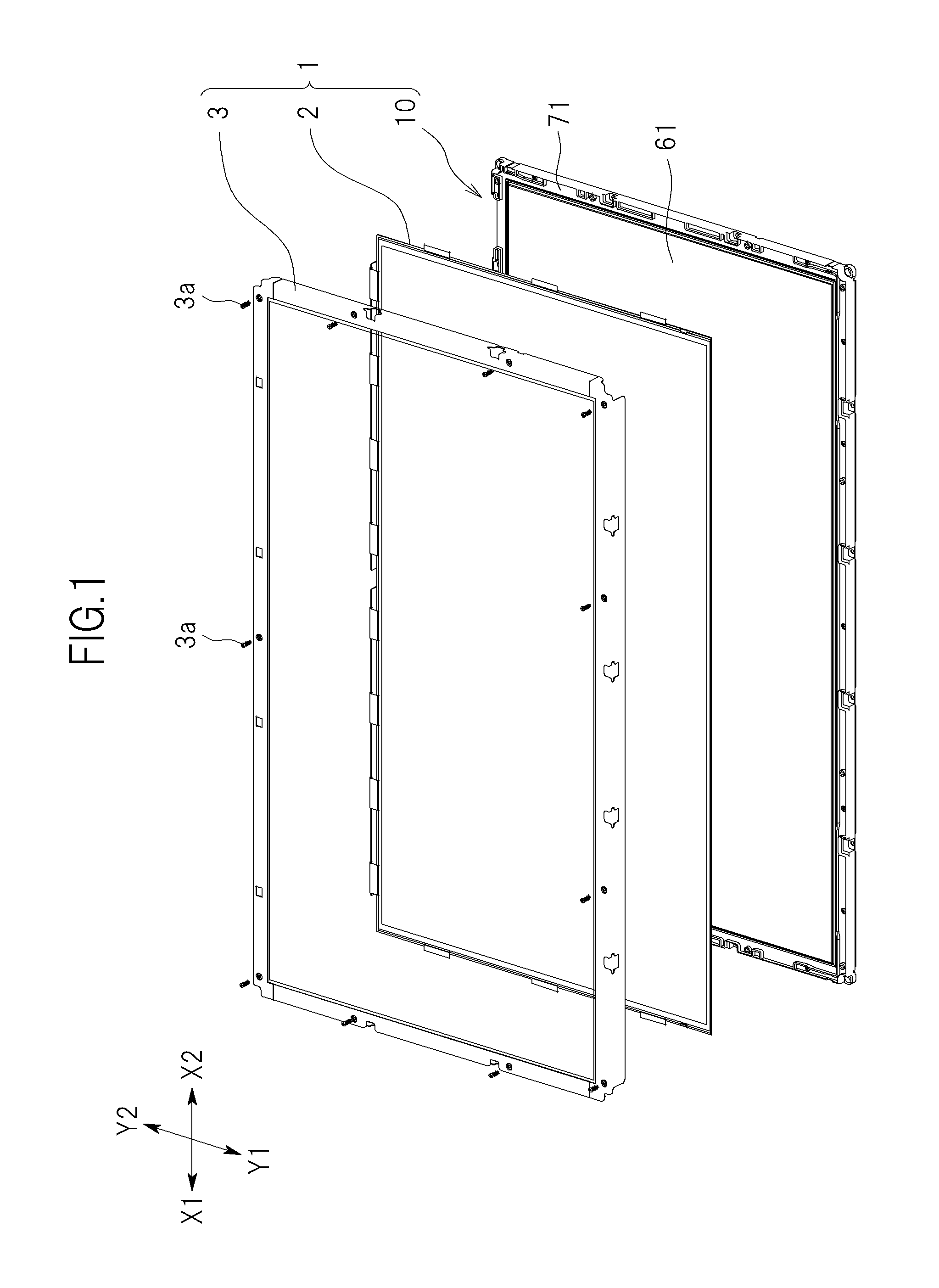
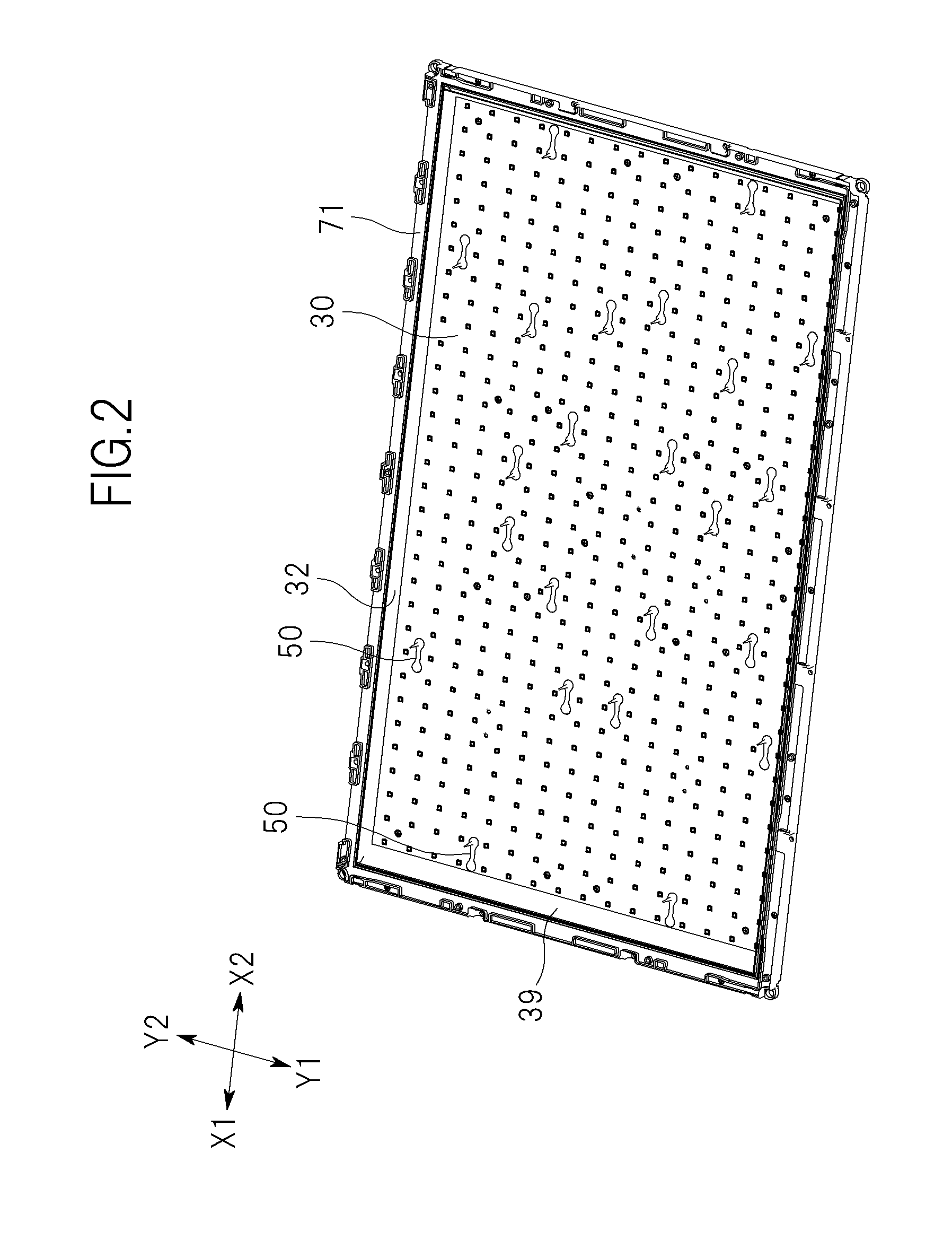
[0024]In the following, one embodiment of the present invention will be described with reference to the accompanying drawings. FIG. 1 is an exploded perspective view of a liquid crystal display device 1 having a backlight unit 10 that is an example of an embodiment of the present invention. FIG. 2 is a perspective view of the backlight unit 10 in which a diffuser panel 62 and an optical sheet 61 of the backlight unit 10 are removed. FIG. 3 is an exploded perspective view of the backlight unit 10. FIG. 4 is an enlarged perspective view of a circuit board 20 of the backlight unit 10. FIG. 5 is a perspective view of a support pin 50 mounted on the circuit board 20. FIG. 6 is a plan view showing a positional relationship between the support pin 50 and the LED's 22 mounted on the circuit board 20. FIG. 7 is a perspective view of the support pin 50 shown in FIG. 7. FIG. 8 is a cross sectional view along the line VIII-VIII shown in FIG. 6.

[0025]As shown in FIG. 1 or 3, the liquid crystal d...


PUM

PropertyMeasurementUnit
widthaaaaaaaaaa
distanceaaaaaaaaaa
sizeaaaaaaaaaa

Abstract

A backlight unit comprises a circuit board (20) having, a plurality of LED's (22) arranged in a matrix, a diffuser panel (62), and a support pin (50) positioned between the circuit board (20) and the diffuser panel (62) for supporting the diffuser panel (62). The support pin (50) includes a first fixation portion (51) inserted in a hole (21) formed on the circuit board (20), a second fixation portion (52) positioned apart from the first fixation portion (51), and a pillar (53) having a tip end supporting the diffuser panel (62). The pillar (53) and the first fixation portion (51) are aligned in a direction perpendicular to the circuit board (20). According to this backlight unit, it is possible to ensure freedom in wiring around the LED's (22) and to prevent the pillar (53) of the support pin (50) from hindering the light.

Description

CROSS-REFERENCE TO RELATED APPLICATION[0001]The present application claims priority from Japanese application JP2010-139839 filed on Jun. 18, 2010, the content of which is hereby incorporated by reference into this application.BACKGROUND OF THE INVENTION[0002]1. Field of the Invention[0003]The present invention relates to a backlight unit for a liquid crystal display device, having a plurality of light sources arranged thereon in a matrix and a liquid crystal display device.[0004]2. Description of the Related Art[0005]Liquid crystal display devices having direct type backlight units have been available. Conventionally, a plurality of fluorescent lamps or light emitting diodes (hereinafter referred to as an LED) arranged in a matrix have been used as a light source for such a type of backlight units.[0006]Japan Patent Publication No. 2009-104978 discloses a backlight unit that utilizes a fluorescent lamp. The backlight unit has a panel-like chassis, a diffuser panel, and a fluorescen...

Claims


Application Information

Patent Timeline
Patent Type & Authority Patents(United States)
IPC IPC(8): G02F1/1335
CPCG02F1/133608
Inventor KITADA, TAKAAKI
Owner PANASONIC INTELLECTUAL PROPERTY CORP OF AMERICA
Learn More