Eureka AIR delivers breakthrough ideas for toughest innovation challenges, trusted by R&D personnel around the world.

Semiconductor device and method of manufacturing semiconductor device

a semiconductor device and semiconductor technology, applied in the direction of semiconductor lasers, semiconductor laser structure details, optical beam sources, etc., can solve the problems of difficult to ensure such high versatility in the form of electrical connection, and achieve the effect of ensuring the freedom of electrical connection, preventing adverse effects on the reliability of the behavior of the semiconductor device, and ensuring the property of heat radiation

Active Publication Date: 2013-12-03
SONY CORP
View PDF10 Cites 0 Cited by
  • Summary
  • Abstract
  • Description
  • Claims
  • Application Information

AI Technical Summary

Benefits of technology

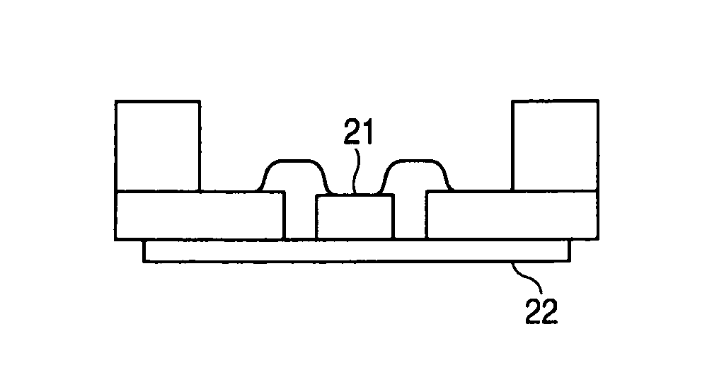
[0008]In this regard, in the case in which the base body 22 is to be formed of a ceramic material, for example, a ceramic multilayer wiring board can be used so that the freedom of electrical connection with the semiconductor laser element 21 can be ensured preferably. The ceramic multilayer wiring board is a board formed of a number of single layer ceramic wiring boards stacked on one another, namely, formed of a layered body of a number of wiring layers. This is because, when using such a ceramic multilayer wiring board as the base body 22, by previously forming the layers so as to be able to respectively correspond to a number of wiring patterns utilizing the number of wiring layers, flexibly coping with switching the wiring for taking out the signals, for example, can be realized easily.
[0010]Therefore, it is desired to provide a semiconductor device capable of achieving high versatility with respect to an electrical connection while ensuring a preferable heat radiation property to prevent an adverse effect caused by heat generation, and a method of manufacturing the semiconductor device.
[0013]As described above, according to a semiconductor device and a method of manufacturing the semiconductor device, the semiconductor element is mounted on the metal plate, and accordingly a preferable heat radiation property can be ensured even if heat is generated in the semiconductor element, and further, heat generation that causes an adverse effect on the reliability of the behavior of the semiconductor device can be prevented. Moreover, since the semiconductor element is electrically connected to the wiring board via the connection terminal, by previously forming the wiring board so as to be able to correspond to a number of wiring patterns, it becomes possible to ensure the freedom of the electrical connection with the semiconductor element preferably. Accordingly, it becomes possible to correspond to various connection forms with respect to the electrical connection with the semiconductor element so that it can cope with the switching of wiring for taking out the signals from the semiconductor element without making any changes in the internal structure of the semiconductor device, and thus the freedom of the electrical connection with the semiconductor element can be ensured preferably to realize high versatility.
[0014]Therefore, according to the semiconductor device and the manufacturing method thereof of the present embodiment, it becomes possible to realize a high versatility with respect to the electrical connection while ensuring a preferable heat radiation property so as to prevent an adverse effect caused by heat generation.

Problems solved by technology

However, if the ceramic multilayer wiring board is used as the base body 22, such a preferable heat radiation property, as in the case of using a metal material with a high heat conductivity, cannot be expected.
On the other hand, if the base body 22 is formed of a metal material, it becomes difficult to ensure such high versatility with respect to the form of electrical connection as in the case of using the ceramic multilayer wiring board.

Method used


Image

  • Semiconductor device and method of manufacturing semiconductor device
  • Semiconductor device and method of manufacturing semiconductor device
  • Semiconductor device and method of manufacturing semiconductor device

Examples


Embodiment Construction

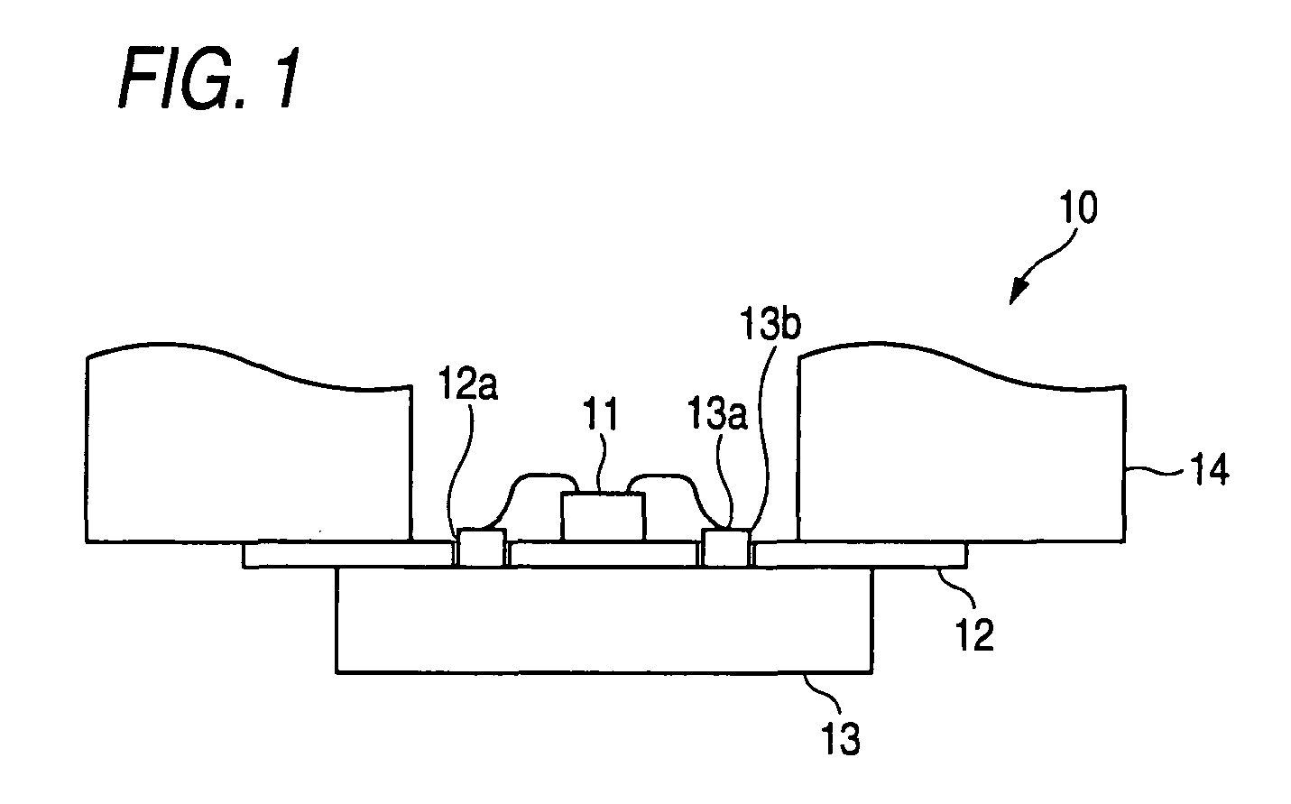
[0020]A semiconductor device and a method of manufacturing a semiconductor device according to an embodiment of the invention will hereinafter be explained with reference to the accompanying drawings. It should be noted that the invention is described in the present embodiment exemplifying, as the semiconductor device, a semiconductor laser device configured so as to be provided with a semiconductor laser element.

[0021]First, a schematic configuration of the semiconductor laser device will be explained.

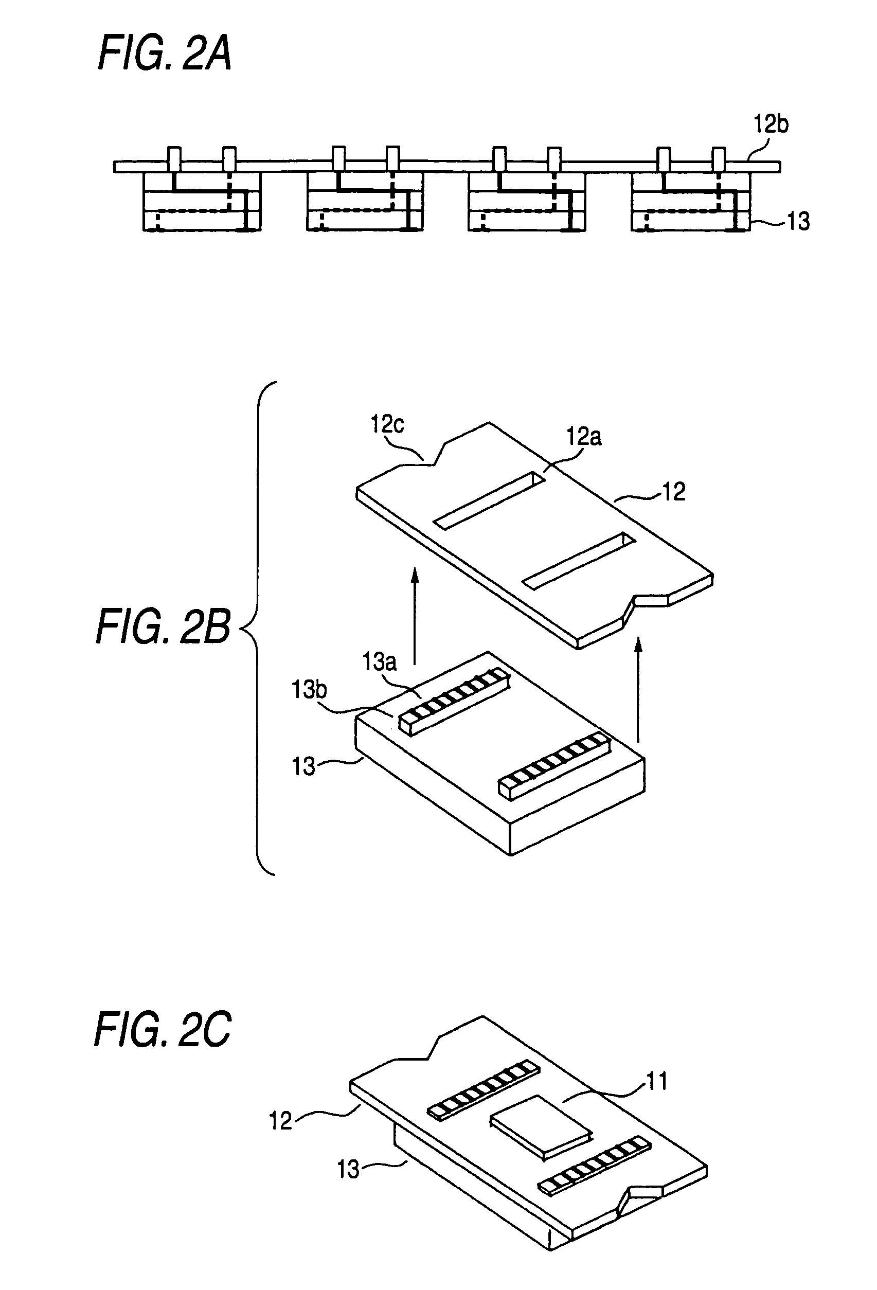
[0022]FIG. 1 is an explanatory view showing a schematic configuration example of the semiconductor laser device applying an embodiment of the invention. As exemplified in the drawing, the semiconductor laser device 10 described in the present embodiment is provided with a semiconductor laser element 11, a lead frame 12 (a metal plate of the embodiment of the invention), a ceramic multilayer wiring board 13 (a wiring board of the embodiment of the invention; hereinafter simply referred...


PUM


Abstract

A semiconductor device includes: a semiconductor element; a wiring board including a connection terminal to be electrically connected to the semiconductor element; and a metal plate disposed between the semiconductor element and the wiring board; wherein the metal plate is provided with an opening for exposing the connection terminal to the semiconductor element.

Description

CROSS REFERENCES TO RELATED APPLICATIONS[0001]The present invention contains subject matter related to Japanese Patent Application JP 2005-319097 filed in the Japan Patent Office on Nov. 2, 2005, the entire contents of which being incorporated herein by reference.BACKGROUND OF THE INVENTION[0002]1. Field of the Invention[0003]The present invention relates to a semiconductor device configured to be provided with a semiconductor element and a method of manufacturing the semiconductor device.[0004]2. Related Art[0005]In recent years, a semiconductor laser device has been known widely as a semiconductor device. The semiconductor laser device is used for, for example, an optical pickup of a disk drive device, and it is specifically configured to have a semiconductor laser element 21 for emitting a laser beam mounted on a tabular base body 22, as shown in FIGS. 4A and 4B.[0006]In such a semiconductor laser device, heat generation caused by the semiconductor laser element 21 emitting the l...

Claims


Application Information

Patent Timeline
Patent Type & Authority Patents(United States)
IPC IPC(8): H01L33/00H01L23/12H01S5/0232
CPCH01L33/64H01S5/02244H01L33/62H01S5/02276H01L2224/48091H01L2924/00014H01S5/0231H01S5/02345H01S5/0232H01S5/02H01L23/12G11B7/127
Inventor YAMAUCHI, KIYOSHI
Owner SONY CORP
Why Eureka
Eureka Blog
Learn More