
Device and method for processing photographic image data

a technology of photographic image data and processing device, which is applied in the direction of radiation control device, exposure control, instruments, etc., can solve the problems of increasing the size and manufacturing cost of the photographing device, the inability to photograph dynamic scenes (images) that change, and the inability to adjust the dynamic range magnification in accordance with the use conditions. , to achieve the effect of reliably photographing dynamic scenes, and the effect of dynami

Inactive Publication Date: 2010-05-18
SONY SEMICON SOLUTIONS CORP
View PDF36 Cites 0 Cited by
  • Summary
  • Abstract
  • Description
  • Claims
  • Application Information

AI Technical Summary

Benefits of technology

The present invention provides a photographing device and method that can change the dynamic range of magnification for dynamic scenes, ensuring reliable photography. The device allows for flexibility in the spatial pattern of sensitivity for light-receiving elements, making it possible to photograph dynamic scenes. The device can also discharge electric charges accumulated in all light-receiving elements at a given timing, ensuring that all light-receiving elements are ready for the next scene. Overall, the invention provides a photographing device and method that can reliably capture and capture high-dynamic range images.

Problems solved by technology

The first method inevitably increases the size and manufacturing cost of the photographing device that adopts this method.
Therefore, the second method cannot photograph dynamic scenes (images) that change, in light intensity, from moment to moment.
In the third method, however, the dynamic range magnification hardly can be adjusted in accordance with the use conditions, because each light-receiving element of the CCD image sensor has but a fixed sensitivity.
The method can indeed increase the dynamic range, but cannot photograph dynamic scenes which change, in light intensity, from moment to moment.
The method disclosed in Jpn. Pat. Appln. Laid-Open Publication 9-191099 has another problem.
No freedom of designing the spatial pattern of sensitivity can be attained in the process of bonding the filters to the light-receiving elements.
Consequently, the CCD image sensor cannot generate signals of three or more different types, each type generated for a different exposure time.
This reduces the freedom of designing the spatial pattern of the PDs 8.

Method used


Image

  • Device and method for processing photographic image data
  • Device and method for processing photographic image data
  • Device and method for processing photographic image data

Examples


Embodiment Construction

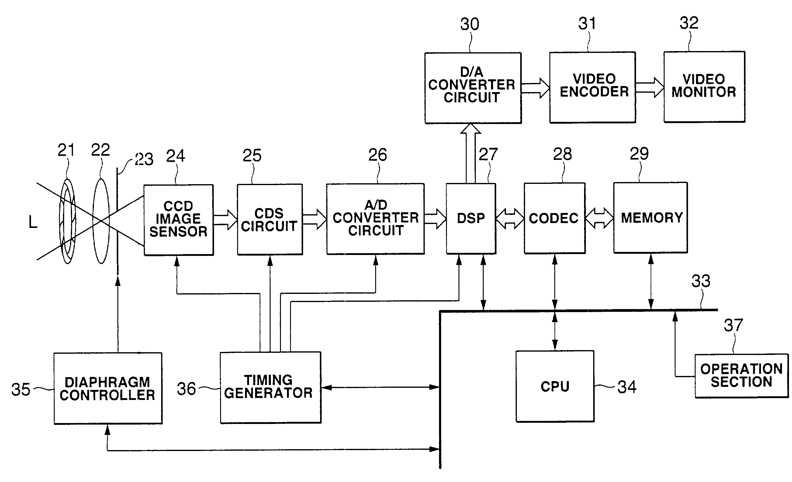
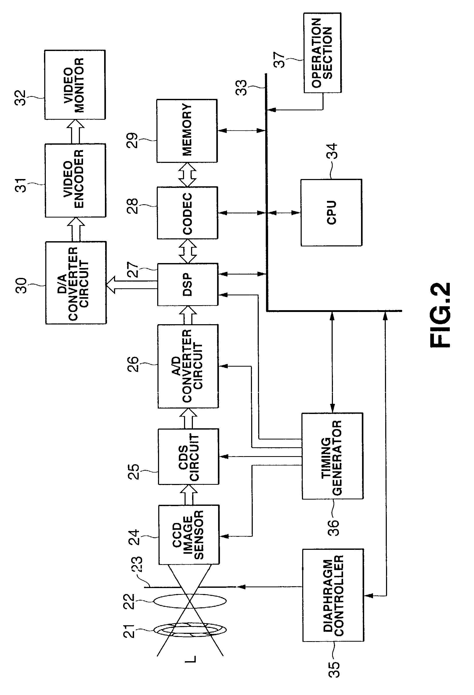
[0095]FIG. 2 is a block diagram of a digital still camera according to the present invention. The light L reflected from an object (not shown) passes through a shutter 21 and a lens 22. A diaphragm 23 adjusts the intensity of the light L to an appropriate value. The light L thus adjusted is applied to a CCD image sensor 24. The focal point of the lens 22 is adjusted so that the light L reflected from the object (not shown) may form an image on the CCD image sensor 24.

[0096]The CCD image sensor 24 includes a number of light-receiving elements (i.e., PDs 8 shown in FIG. 12, which will be later described). The CCD image sensor 24 performs photoelectric conversion on the light L applied to it via the lens 22 and the diaphragm 23. In other words, it converts an image of the object to an electric signal. The electric signal is supplied to a CDS (Correlated Double Sampling) circuit 25.

[0097]The CDS circuit 25 receives the electric signal from the CCD image sensor 24 and compares the signal...


PUM


Abstract

Disclosed herein is a photographing device that includes a number of light-receiving elements, a number of vertical transfer registers, a first drive-voltage applying electrode, and a second drive-voltage applying electrode. The light-receiving elements are arranged in a horizontal direction and a vertical direction. The vertical transfer registers transfers the electric charges accumulated in the light-receiving elements in the vertical direction. The first drive-voltage applying electrode is arranged parallel to the vertical transfer registers, for applying a drive voltage to a specific one of the vertical transfer registers. The second drive-voltage applying electrode is arranged perpendicular to the vertical transfer registers, for applying a second drive voltage to the vertical transfer registers at the same time. The electric charges accumulated in the light-receiving elements are transferred to the vertical transfer registers, due to the voltage output from the first drive-voltage applying electrode or the second drive-voltage applying electrode, or the voltages output from both electrodes. Therefore, the light-receiving elements can have different sensitivities, and the photographing device can photograph dynamic scenes in a broad dynamic range.

Description

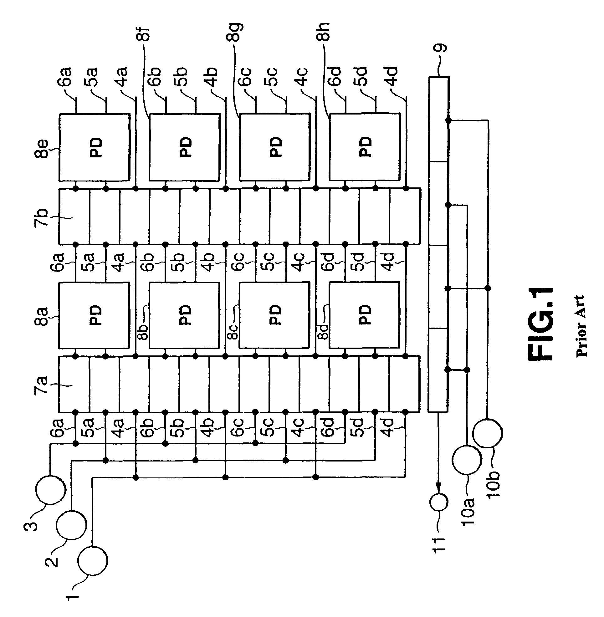
BACKGROUND OF THE INVENTION[0001]The present invention relates to a photographing device and a photographing method. More particularly, the present invention relates to a photographing device and a photographing method, in which the dynamic range magnification can be changed as desired and which can reliably photograph dynamic scenes, too.[0002]Photographing devices incorporating a CCD (Charged Coupled Device) image sensor are widely used.[0003]A CCD image sensor is a solid-state photographing element. It finds use in various photographing devices such as video cameras and digital still cameras. Photographing devices, each including a CCD image sensor, are widely used in parts inspection apparatuses in FA (Factory Automation) and optical apparatuses in ME (Medical Electronics), such as electronic endoscopes.[0004]FIG. 1 shows the electrical configuration of an interline-type CCD image sensor for use in conventional photographing devices.[0005]The image sensor includes a first-phase ...

Claims


Application Information

Patent Timeline
Patent Type & Authority Patents(United States)
IPC IPC(8): H04N5/235G03B7/00H01L27/148H04N5/355
CPCH01L27/1462H01L27/14812H04N5/35554H04N3/155H04N5/235H01L27/1485H04N23/70H04N25/583H04N25/73H04N25/133
Inventor HARADA, KOUICHIMITSUNAGA, TOMOOKOBAYASHI, SEIJI
Owner SONY SEMICON SOLUTIONS CORP
Learn More