Distributed intelligent routing method for unmanned aerial vehicle network slices

A machine network, distributed technology, applied in the field of distributed intelligent routing for UAV network slicing, to achieve the effect of fast path selection

Active Publication Date: 2020-04-24
UNIV OF ELECTRONICS SCI & TECH OF CHINA
View PDF11 Cites 16 Cited by
  • Summary
  • Abstract
  • Description
  • Claims
  • Application Information

AI Technical Summary

Problems solved by technology

The purpose of the present invention is to provide a distributed intelligent routing method for UAV network slicing, to solve the problem of how to improve communication quality in the dynamic network environment of UAV network slicing scenarios

Method used


Image

  • Distributed intelligent routing method for unmanned aerial vehicle network slices
  • Distributed intelligent routing method for unmanned aerial vehicle network slices
  • Distributed intelligent routing method for unmanned aerial vehicle network slices

Examples


Embodiment 1

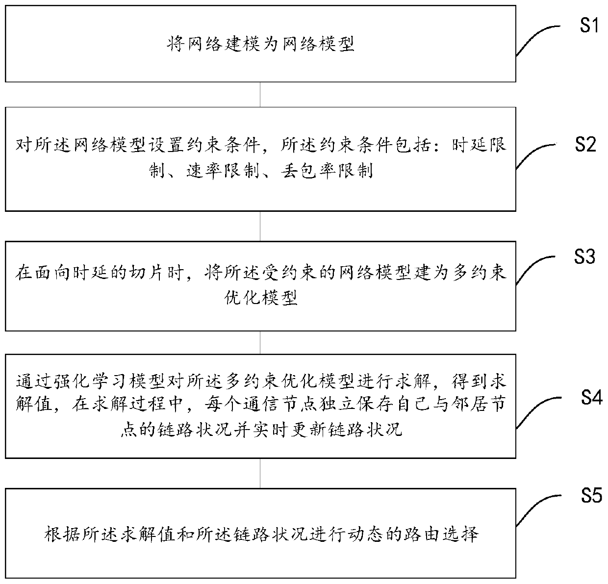
[0049] Such as figure 1shown. Embodiment 1 is a distributed intelligent routing method for UAV network slicing. First, by modeling the UAV network as a network model; then setting constraints on the network model, the constraints include: delay limit, rate limit, packet loss rate limit; when facing low-latency slices, The constrained network model is built as a multi-constraint optimization model; then the multi-constraint optimization model is solved by a reinforcement learning model to obtain a solution value. During the solution process, each communication node independently saves the link status and update the link status in real time; and then perform dynamic route selection according to the solution value and the link status.

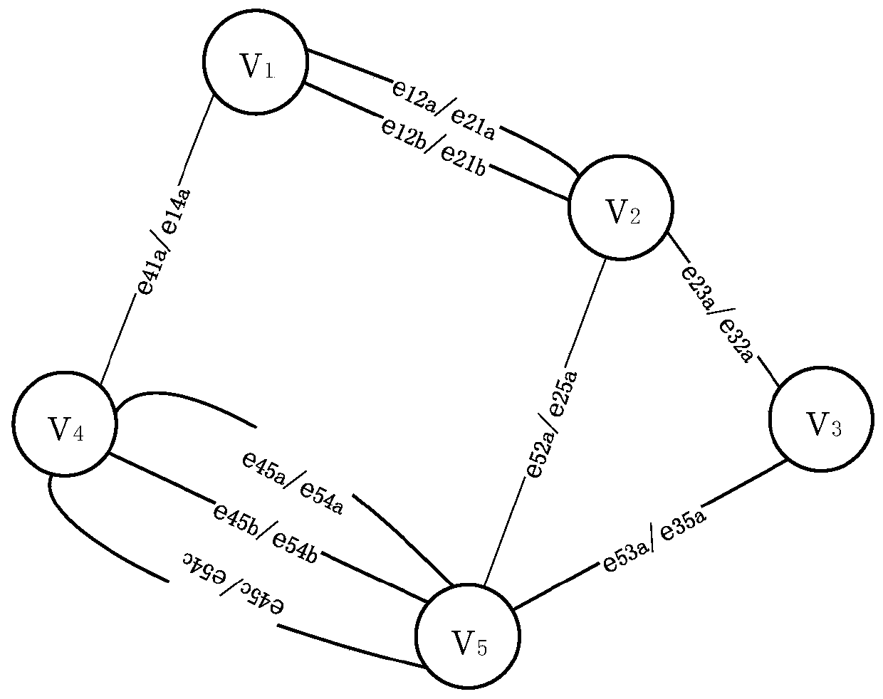
[0050] In a static network environment, the network model in Embodiment 1 is established as an undirected graph G(V, E, W) with weighted edges, where V is the set of communication nodes in the network, expressed as V={v 1 ,v 2 ,...,v n}, n is...

Embodiment 2

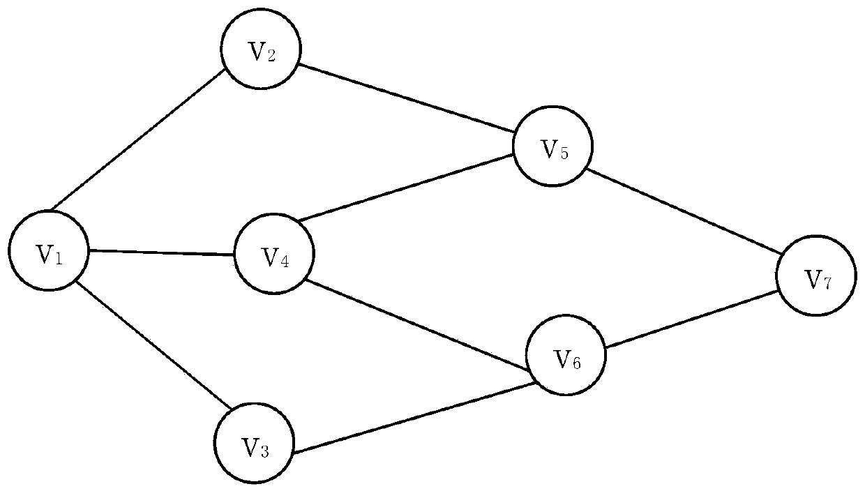
[0071] by image 3 The specific process of Q-learning is introduced as an example. Find a path from v1 to v7 that meets the QoS requirements. Designate each node as a state, in image 3 In the network shown, the number of states is 7. In each state, the action is defined as the optional next hop of each node. Taking v1 as an example, the size of its action set is 3, and there are three optional actions: v2, v3, and v4. Three Q values ​​are defined in each state, which are respectively used to describe the delay, packet loss rate, and bandwidth from the current node to the destination node. v1 first uses the ε-greedy strategy to send data packets, and judges which node the next hop of the data packet should be sent to according to the Q value of v2, v3, and v4. If the packet loss rate and bandwidth meet the requirements when v2 is selected (judged by Q12(e) and Q12(v)), update Q12(d), and repeat the same steps for v2 until v7 is selected, and an iterative process is complet...

Embodiment 3

[0075] Suppose a service flow in the current network initiates a routing request, its source node is s, destination node is d, Q ij (d), Q ij (e) and Q ij (v) respectively represent the cumulative link delay, cumulative packet loss rate and path rate from the current node to the destination node d, ∞ represents infinity, each node will maintain its own three types of Q value information, Indicates the neighbor node i of node j, and l indicates the experimental round.

[0076] Now known: the source node s of the service flow, the destination node j, the service type (here, the low-latency service is taken as an example), and the QoS requirement;

[0077] The purpose is to obtain: the path selection scheme π of this service.

[0078] Initialization phase:

[0079]

[0080] Qij (d)=∞,Q ij (e)=1,Q ij (v)=0 / / initialize Q-value

[0081] Online learning phase:

[0082]

[0083]

[0084] output:


PUM


Abstract

The invention discloses a distributed intelligent routing method for unmanned aerial vehicle network slices. The method comprises the following steps: modeling an unmanned aerial vehicle network intoa network model; setting constraint conditions for the network model, wherein the constraint conditions comprise time delay limitation, rate limitation and packet loss probability limitation; establishing a constrained network model into a multi-constraint optimization model during slicing oriented to low time delay; solving the multi-constraint optimization model through a reinforcement learningmodel to obtain a solving value, and in the solving process, independently storing the link condition of each communication node and a neighbor node and updating the link condition in real time by each communication node; and carrying out dynamic routing selection according to the solving value and the link condition. The method effectively solves the problems that in the prior art, a routing method cannot adapt to the characteristics that an unmanned aerial vehicle network has high time delay requirements and the network dynamically changes at any time. According to the invention, the technical blank is filled, and better conditions are created for the unmanned aerial vehicle network environment.

Description

technical field [0001] The invention relates to a wireless network routing method, in particular to a distributed intelligent routing method for unmanned aerial vehicle network slicing. Background technique [0002] The traditional algorithm based on the shortest path algorithm to solve the routing policy will be difficult to apply to the scenario of UAV network slicing. This is because the current network is not adaptable to the real-time changing network environment, and the path selected by the shortest path algorithm is relatively single. When the number of business flows in the network gradually increases, the possibility of network congestion will increase significantly. On the basis of the shortest path algorithm, if the degree of network congestion is expected to be reduced, the number of business flows that can be carried will be sacrificed. In addition, in actual scenarios, due to the mobility of nodes, the communication quality of links in the network will also c...

Claims


Application Information

Patent Timeline
Patent Type & Authority Applications(China)
IPC IPC(8): H04W16/22H04W40/12H04W40/22H04W40/24
CPCH04W16/22H04W40/12H04W40/22H04W40/248Y02T10/40
Inventor 陈博伦孙耀秦爽冯钢
Owner UNIV OF ELECTRONICS SCI & TECH OF CHINA
Why Eureka
Try Eureka