A Distributed Intelligent Routing Method for UAV Network Slicing
A machine network and distributed technology, applied in the field of distributed intelligent routing for UAV network slicing, to achieve the effect of fast path selection
- Summary
- Abstract
- Description
- Claims
- Application Information
AI Technical Summary
Problems solved by technology
Method used
Image
Examples
Embodiment 1
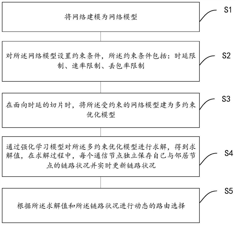
[0049] Such as figure 1shown. Embodiment 1 is a distributed intelligent routing method for UAV network slicing. First, by modeling the UAV network as a network model; then setting constraints on the network model, the constraints include: delay limit, rate limit, packet loss rate limit; when facing low-latency slices, The constrained network model is built as a multi-constraint optimization model; then the multi-constraint optimization model is solved by a reinforcement learning model to obtain a solution value. During the solution process, each communication node independently saves the link status and update the link status in real time; and then perform dynamic route selection according to the solution value and the link status.
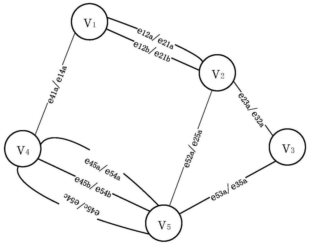
[0050] In a static network environment, the network model in Embodiment 1 is established as an undirected graph G(V, E, W) with weighted edges, where V is the set of communication nodes in the network, expressed as V={v 1 ,v 2 ,...,v n}, n is...
Embodiment 2
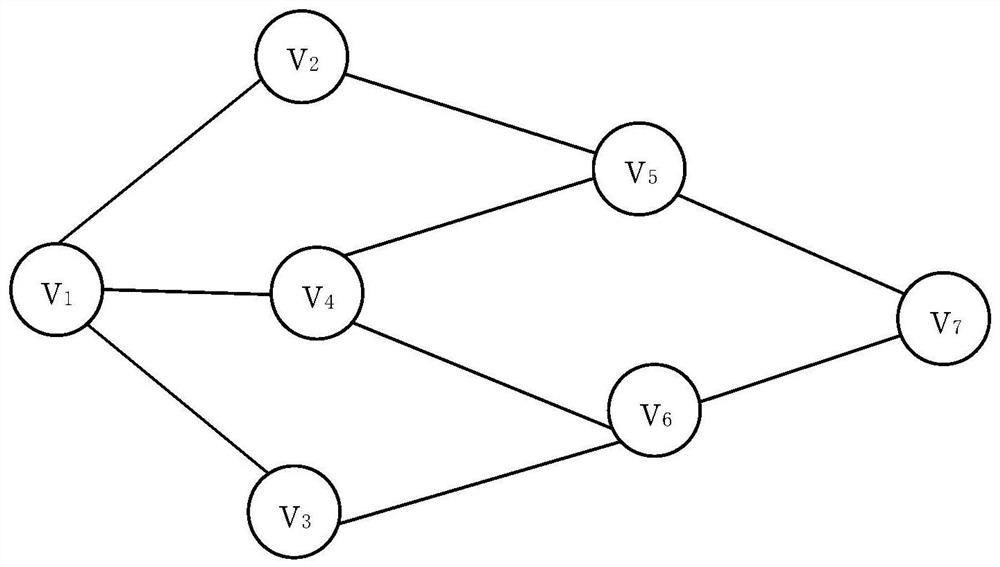
[0071] by image 3 The specific process of Q-learning is introduced as an example. Find a path from v1 to v7 that meets the QoS requirements. Designate each node as a state, in image 3 In the network shown, the number of states is 7. In each state, the action is defined as the optional next hop of each node. Taking v1 as an example, the size of its action set is 3, and there are three optional actions: v2, v3, and v4. Three Q values are defined in each state, which are respectively used to describe the delay, packet loss rate, and bandwidth from the current node to the destination node. v1 first uses the ε-greedy strategy to send data packets, and judges which node the next hop of the data packet should be sent to according to the Q value of v2, v3, and v4. If the packet loss rate and bandwidth meet the requirements when v2 is selected (judged by Q12(e) and Q12(v)), update Q12(d), and repeat the same steps for v2 until v7 is selected, and an iterative process is complet...
Embodiment 3
[0075] Suppose a service flow in the current network initiates a routing request, its source node is s, destination node is d, Q ij (d), Q ij (e) and Q ij (v) respectively represent the cumulative link delay, cumulative packet loss rate and path rate from the current node to the destination node d, ∞ represents infinity, each node will maintain its own three types of Q value information, Indicates the neighbor node i of node j, and l indicates the experimental round.
[0076] Now known: the source node s of the service flow, the destination node j, the service type (here, the low-latency service is taken as an example), and the QoS requirement;
[0077] The purpose is to obtain: the path selection scheme π of this service.
[0078] Initialization phase:
[0079]
[0080] Qij (d)=∞,Q ij (e)=1,Q ij (v)=0 / / initialize Q-value
[0081] Online learning phase:
[0082]
[0083]
[0084] output:
PUM
 Abstract
Description
Claims
Application Information
 - R&D
- Intellectual Property
- Life Sciences
- Materials
- Tech Scout
- Unparalleled Data Quality
- Higher Quality Content
- 60% Fewer Hallucinations
Browse by: Latest US Patents, China's latest patents, Technical Efficacy Thesaurus, Application Domain, Technology Topic, Popular Technical Reports.
© 2025 PatSnap. All rights reserved.Legal|Privacy policy|Modern Slavery Act Transparency Statement|Sitemap|About US| Contact US: help@patsnap.com


