Eureka AIR delivers breakthrough ideas for toughest innovation challenges, trusted by R&D personnel around the world.

Drive force transmission device

a transmission device and drive force technology, applied in the direction of gearing details, couplings, gearing, etc., can solve the problem that the oil temperature sensor cannot detect the oil temperature exactly

Active Publication Date: 2018-03-06
HONDA MOTOR CO LTD
View PDF22 Cites 0 Cited by
  • Summary
  • Abstract
  • Description
  • Claims
  • Application Information

AI Technical Summary

Benefits of technology

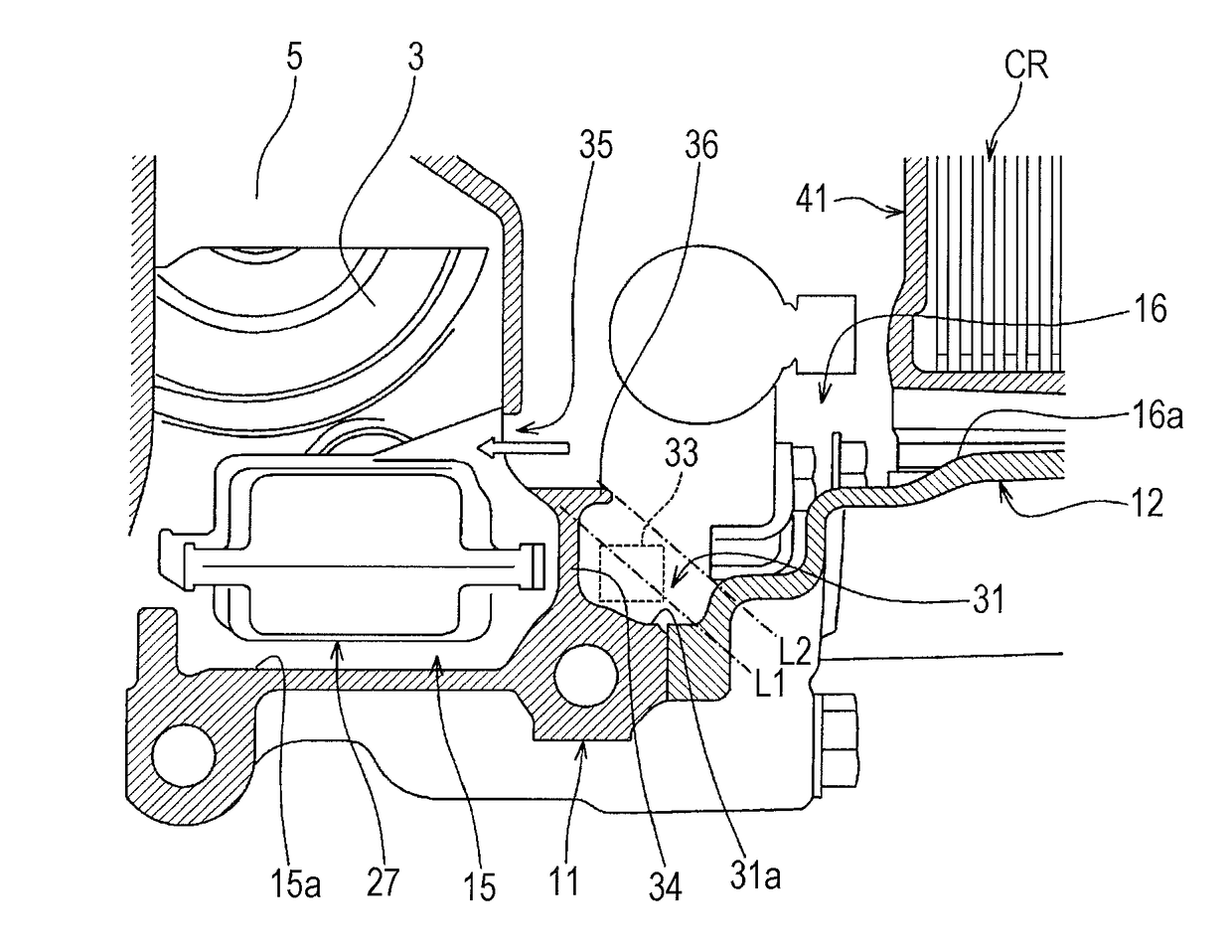
[0049]In the drive force transmission device according to an embodiment of the present disclosure, the freedom in the arrangement of the drive force transmission device and other components can be ensured with a simple structure, and an oil temperature sensor can still remain in a hydraulic oil even when an oil surface of the hydraulic oil is inclined in accordance with the running state of a vehicle.

Problems solved by technology

Accordingly, there may be a case in which the oil temperature sensor cannot exactly detect the oil temperature.

Method used


Image

  • Drive force transmission device
  • Drive force transmission device
  • Drive force transmission device

Examples


Embodiment Construction

[0015]The embodiments will now be described with reference to the accompanying drawings, wherein like reference numerals designate corresponding or identical elements throughout the various drawings.

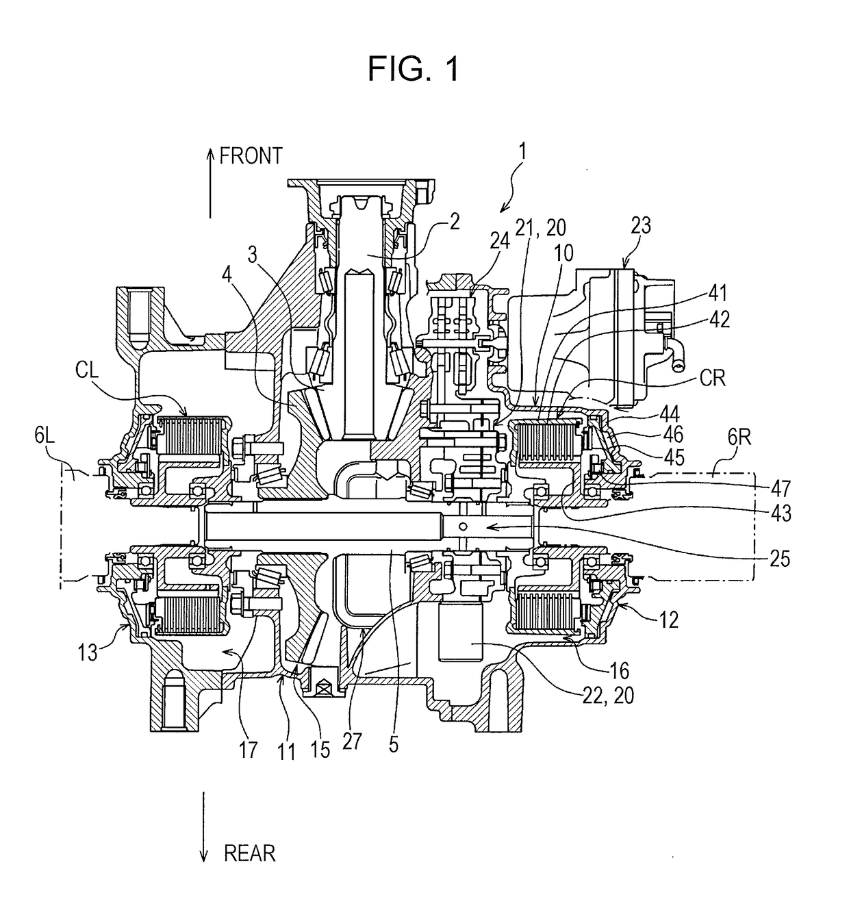
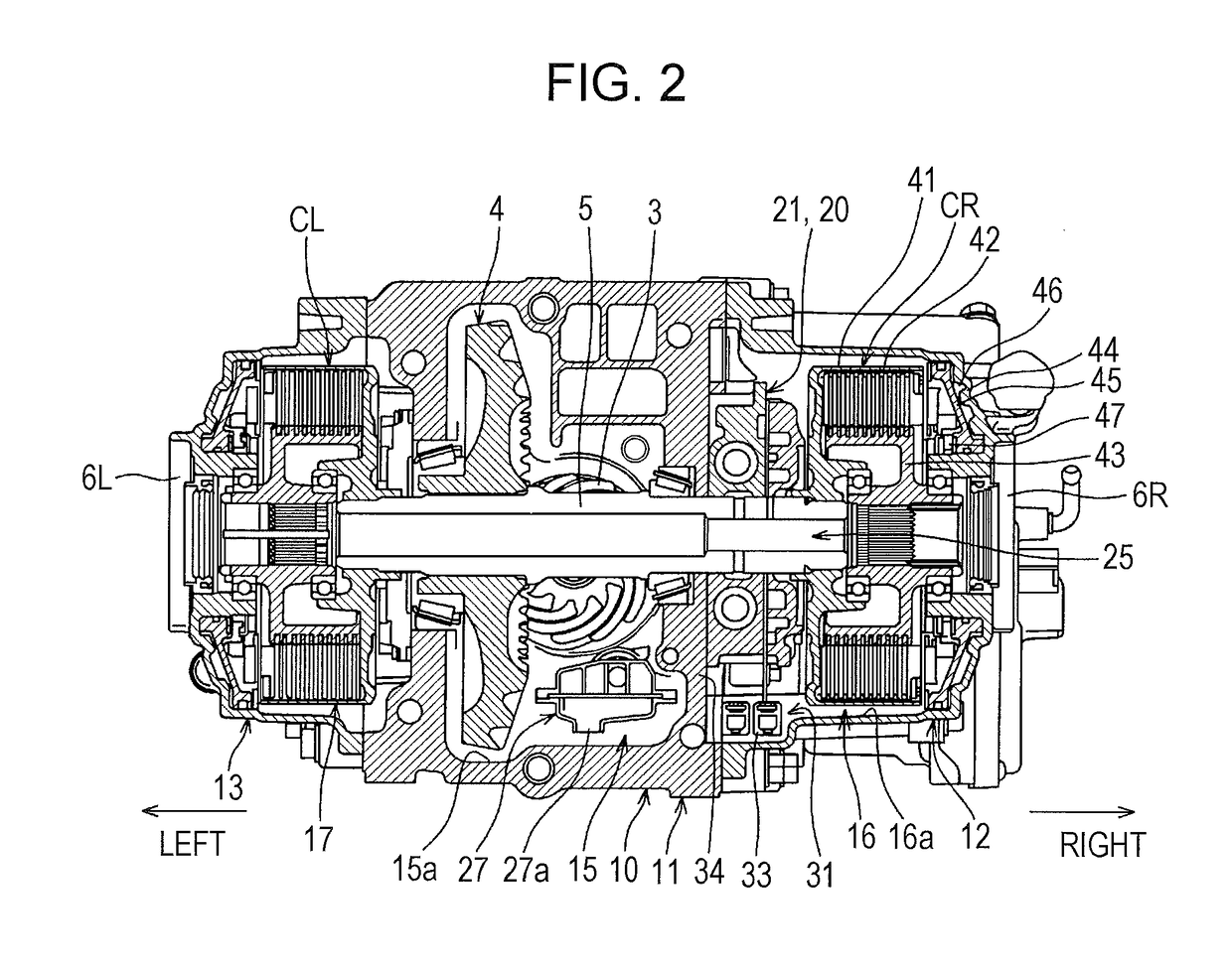
[0016]An embodiment of the present disclosure will be described in detail below with reference to the accompanying drawings. FIG. 1 is a main sectional view (sectional view in plan view) of a drive force transmission device according to an embodiment of the present disclosure. FIG. 2 is a side sectional view of the drive force transmission device. Referring to FIG. 1, a drive force transmission device 1 includes a hypoid pinion shaft 2, a hypoid pinion gear 3, and a hypoid ring gear 4. The hypoid pinion shaft 2 is connected to a propeller shaft (not shown), which is rotated by a drive force transmitted from an engine (not shown). The hypoid pinion gear 3 is formed at a tip end of the hypoid pinion shaft 2. The hypoid ring gear 4 is engaged with the hypoid pinion gear 3.

[0017]The hypoid r...


PUM


Abstract

A drive force transmission device provided in a vehicle includes a rotating shaft, a gear chamber, a first clutch chamber, a hydraulic oil supplier, an oil reservoir, and an oil temperature sensor. The rotating shaft extends in an axial direction and is rotatable around the axial direction to transmit a drive force to left and right drive wheels of the vehicle. The gear chamber houses a gear via which the drive force is to be transmitted to the rotating shaft. The drive force transmission device has a first side and a second side opposite to the first side with respect to the gear chamber in the axial direction. The first clutch chamber is disposed on the first side and houses a clutch that is to distribute the drive force transmitted from the rotating shaft to the left or right drive wheels.

Description

CROSS-REFERENCE TO RELATED APPLICATIONS[0001]The present application claims priority under 35 U.S.C. § 119 to Japanese Patent Application No. 2013-070621, filed Mar. 28, 2013, entitled “Drive Force Transmission Device.” The contents of this application are incorporated herein by reference in their entirety.BACKGROUND[0002]1. Field[0003]The present disclosure relates to a drive force transmission device.[0004]2. Description of the Related Art[0005]An automatic transmission installed in a vehicle or the like includes an oil temperature sensor that detects an oil temperature of a hydraulic oil (lubricant) supplied to a casing of the transmission. In such an automatic transmission equipped with the oil temperature sensor, when an oil surface in the casing is inclined by the centrifugal force generated by a turn of the vehicle, inclination of a road surface, or the like, a detection unit of the oil temperature sensor may be exposed from the oil surface in the casing depending on a positi...

Claims


Application Information

Patent Timeline
Patent Type & Authority Patents(United States)
IPC IPC(8): F16D48/02F16D25/10F16H57/02F16H48/22F16H57/04F16D48/06F16D25/12F16H59/72
CPCF16D25/10F16D25/123F16D48/02F16D48/062F16H48/22F16H57/045Y10T74/19614F16D2300/26F16D2500/1026F16D2500/10412F16D2500/3056F16D2500/70448F16H59/72F16D2300/18
Inventor TSUCHIHASHI, MAKOTOOTANI, TETSUYA
Owner HONDA MOTOR CO LTD
Why Eureka
Eureka Blog
Learn More