Watercraft

a watercraft and water body technology, applied in the field of watercraft, can solve the problems of large turning circle, unwieldy construction, and relative poor maneuverability of watercraft, and achieve the effect of reducing the resistance of watercraft at high speed, high speed, and high speed

Active Publication Date: 2015-03-03
WESP EURO NV
View PDF13 Cites 2 Cited by
  • Summary
  • Abstract
  • Description
  • Claims
  • Application Information

AI Technical Summary

Benefits of technology

[0019]A watercraft according to the invention that has such a foil profile provides the advantage that the resistance that the watercraft experiences at high speeds is kept to a minimum, as the front part of the watercraft that takes the bulk of the weight of a passenger is barely in contact with the water, but only via the aforementioned foil profile.
[0020]As a result, higher speeds can be reached with a watercraft according to the invention than with the known watercrafts of the same type, at least insofar both watercrafts are driven with the same force.
[0021]On the other hand, to obtain the same relatively high speed, less energy or force is required in a watercraft according to the invention than with known watercrafts of the same type.

Problems solved by technology

A disadvantage of the known watercrafts of this type is that they are relatively poorly maneuverable and that the radius of the turning circle when making a turn with such a watercraft is rather large.
Another disadvantage of the known watercrafts of the aforementioned type is that they often have a very unwieldy construction.
A further disadvantage of the known watercrafts of the aforementioned type is that they present a relatively high resistance when sailing, especially at high speeds.
Sailing at high speeds with such known watercrafts thus requires an enormous amount of energy and / or powerful engines, with high costs as a result.

Method used


Image

  • Watercraft
  • Watercraft
  • Watercraft

Examples


Embodiment Construction

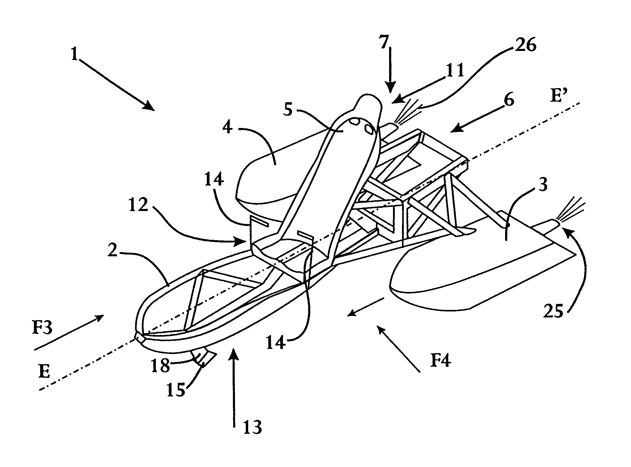
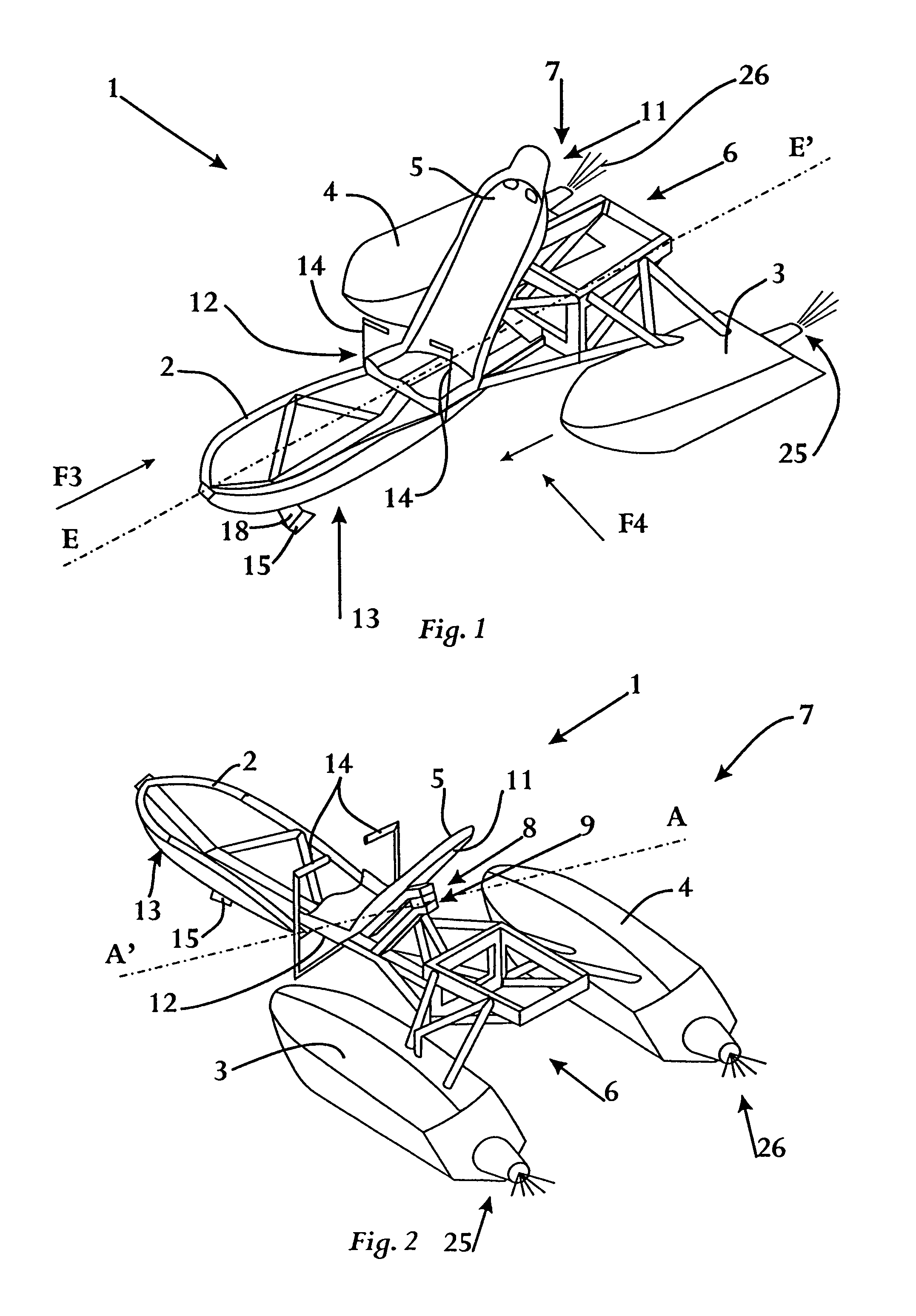
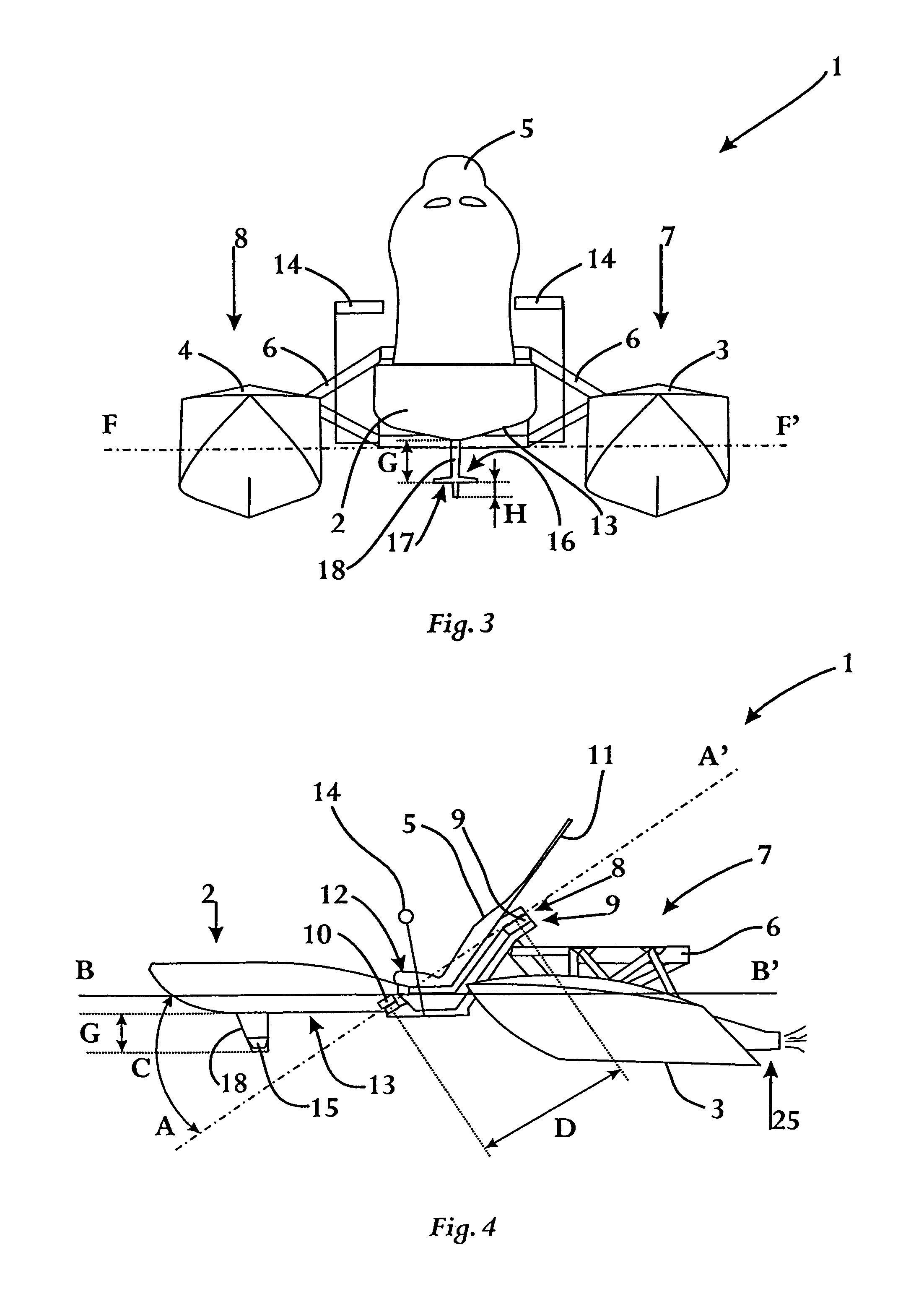
[0027]The watercraft 1 according to the invention shown in FIGS. 1 to 4 is a watercraft intended for recreational use, for example for making pleasure trips or practising water sports or similar.

[0028]These FIGS. 1 to 4 are only simple illustrations of a possible embodiment of a watercraft 1 according to the invention, whereby the characteristics of the watercraft 1 that are important for the invention are made clear, but other parts of the watercraft 1 are not shown, such as a drive means or other structural elements that can form the actual superstructure of the watercraft 1, such as for example a deck, a load platform, a railing or similar.

[0029]The watercraft 1 consists of a mid section 2 and two side sections 3 and 4.

[0030]The mid section 2 is constructed as a kind of tub, while the side sections 3 and 4 are floating floats formed by hollow closed chambers that are filled with air or a light material such as a foam rubber or similar.

[0031]Of course it is the intention that thes...


PUM


Abstract

A watercraft, including; a mid section (2) and two side sections (3,4), whereby the mid section (2) has a seat (5) for a passenger and whereby the watercraft (1) has a steering mechanism. The watercraft (1) includes a front part (2) and a rear part, relative to a direction of travel of the watercraft (7), that are coupled together by means of a hinged coupling (8). The front part (2) of the watercraft (1) includes the mid section (2) of the watercraft (1), and the rear part (7) of the watercraft (1) includes the two side sections (3,4). The hinged coupling (8) forms part of the steering mechanism, such that as a result of a rotation of the front part (2) with respect to the rear part (7) of the watercraft (1) around the hinged coupling (8), the direction of travel of the watercraft (1) is changed.

Description

FIELD OF THE INVENTIONBackground of the Invention[0001]More specifically the invention relates to a watercraft intended for recreational use that consists of a mid section and two side sections, with which sections the watercraft can float on water, whereby the mid section has a seat for a passenger and whereby the watercraft has a steering mechanism.[0002]Such watercrafts are already known, for example in the form of a speed boat, yacht or similar, that generally have a limited draught and to this end, for reasons relating to the stability of the boat in water, are constructed with a mid section and two side sections with which the boat rests on the water.[0003]A disadvantage of the known watercrafts of this type is that they are relatively poorly maneuverable and that the radius of the turning circle when making a turn with such a watercraft is rather large.[0004]Another disadvantage of the known watercrafts of the aforementioned type is that they often have a very unwieldy constr...

Claims


Application Information

Patent Timeline
Patent Type & Authority Patents(United States)
IPC IPC(8): B63H25/48B63B1/10B63B1/12B63B29/04B63B35/73B63H11/02B63H25/00B63H25/46B63H25/52
CPCB63H25/00B63H25/46B63H25/52B63H11/02B63H25/48B63B1/10B63B1/125B63B29/04B63B35/73B63B1/24B63B2007/003B63B34/10B63B1/105B63B2029/043
Inventor MYNY, PIETER
Owner WESP EURO NV
Why Eureka
Try Eureka