Vessel, in particular pressure vessel

Active Publication Date: 2015-03-03
HYDAC PROCESS TECH
View PDF32 Cites 1 Cited by
  • Summary
  • Abstract
  • Description
  • Claims
  • Application Information

AI Technical Summary

Benefits of technology

[0004]An object of the invention is to provide an improved vessel, in particular a pressure vessel, permitting securing the cover part on a housing part in a

Problems solved by technology

Since the prior art solution has a piston-cylinder system comprises a hydraulically or pneumatically operated annular cylinder with an annular piston that can be displaced upward against the ends of the clamps at the cover, the result is a fail-safe

Method used


Image

  • Vessel, in particular pressure vessel
  • Vessel, in particular pressure vessel
  • Vessel, in particular pressure vessel

Examples


Embodiment Construction

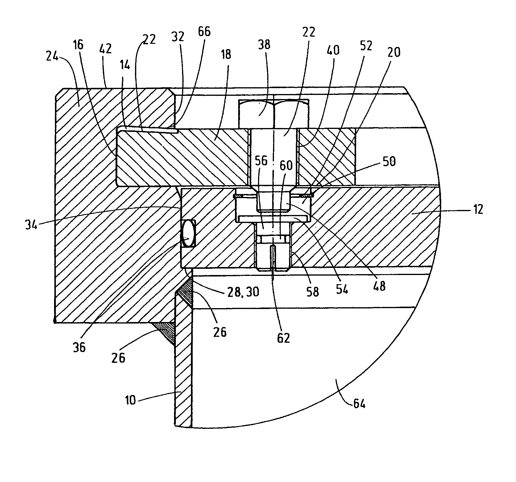
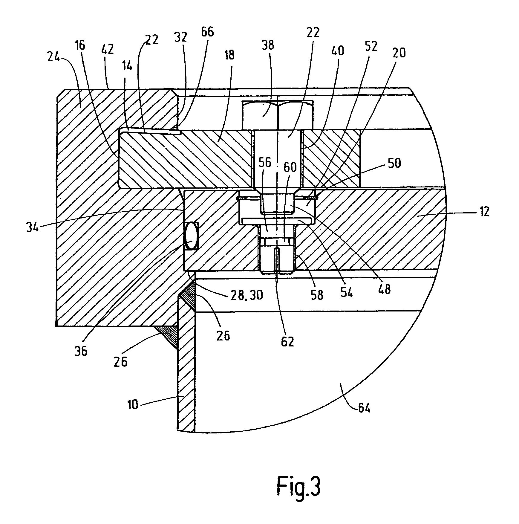
[0020]The vessel, in particular the pressure vessel, has a tubular housing part 10 in which a cover part 12 can be secured. In this case, the contact segments 18 are inserted at least in some areas in an annular housing recess 14 on the interior 16 of the housing part 10 (cf. sectional view according to FIG. 3). These contact segments 18 provide support for the cover part 12 in its installed state (depicted in FIG. 3) with parts of its upper side 20. At least one securing device 22 guarantees a detachable engagement between the cover part 12 and at least one of the contact segments 18.

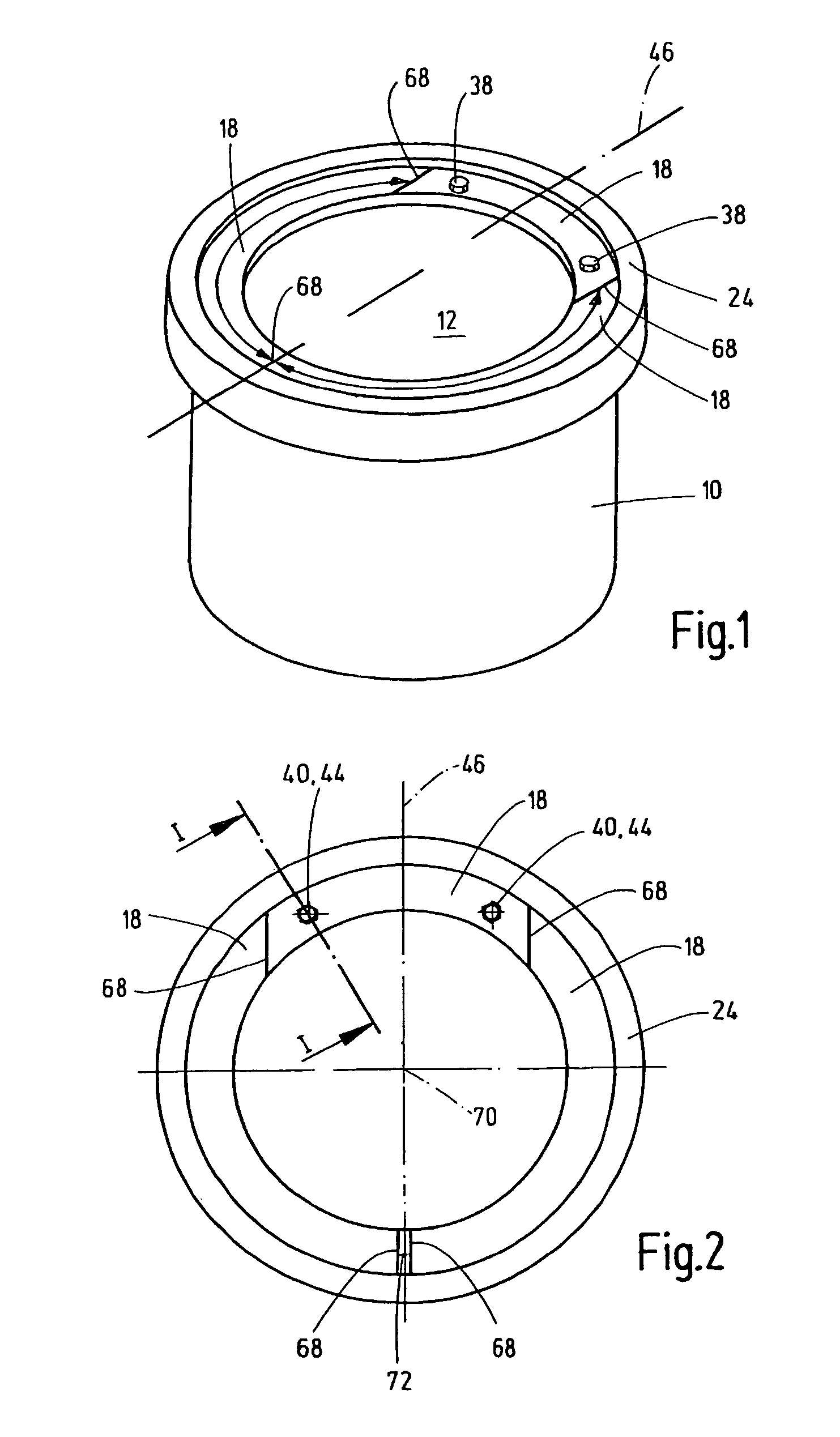
[0021]It is especially clear from FIGS. 1 and 2 that the contact segments 18 have a circular arc shape with a rectangular cross section. The relevant adjacent contact segments 18 abut each other at their end faces. As illustrated in FIG. 3, the tubular housing part 10 has an edge expansion 24 in the direction of its upper free edge. This edge expansion is connected outwardly and inwardly in a sealing m...


PUM


Abstract

A vessel, particularly a pressure vessel, has a tubular housing part (10) in which a cover part (12) can be secured. Support segments (18) are inserted at least in some areas in a recess (14) on the interior (16) of the housing part (10). These segments provide support to the cover part (12) when it is installed. At least one fixing device (22) ensures a releasable engagement between cover part (12) and at least one of the support segments (18).

Description

FIELD OF THE INVENTION[0001]The invention relates to a vessel, in particular a pressure vessel, having a tubular housing part in which a cover part can be secured.BACKGROUND OF THE INVENTION[0002]DE 39 04 816 C1 discloses a pressure vessel, in particular a pressure filter vessel, comprising a cover. The cover has an edge that can be pressed in a sealing manner onto the edge of the vessel with optional interpositioning of a disk by a pressing device. The pressing device has clamps comprising ends, which grip the cover, starting from the pressure vessel. An actuated piston-cylinder system presses axially against these clamps. Since the prior art solution has a piston-cylinder system comprises a hydraulically or pneumatically operated annular cylinder with an annular piston that can be displaced upward against the ends of the clamps at the cover, the result is a fail-safe construction for the known pressure vessel solution with a pressing device. However, the pressure vessel and, in pa...

Claims


Application Information

Patent Timeline
IPC IPC(8): B65D45/00B65D45/32F16J13/08F16J13/10F16J13/24
CPCF16J13/10F16J13/08F16J13/24
Inventor LANG, NORBERTSCHLACHTER, STEFAN
Owner HYDAC PROCESS TECH
Why Eureka
Try Eureka