Electric connector

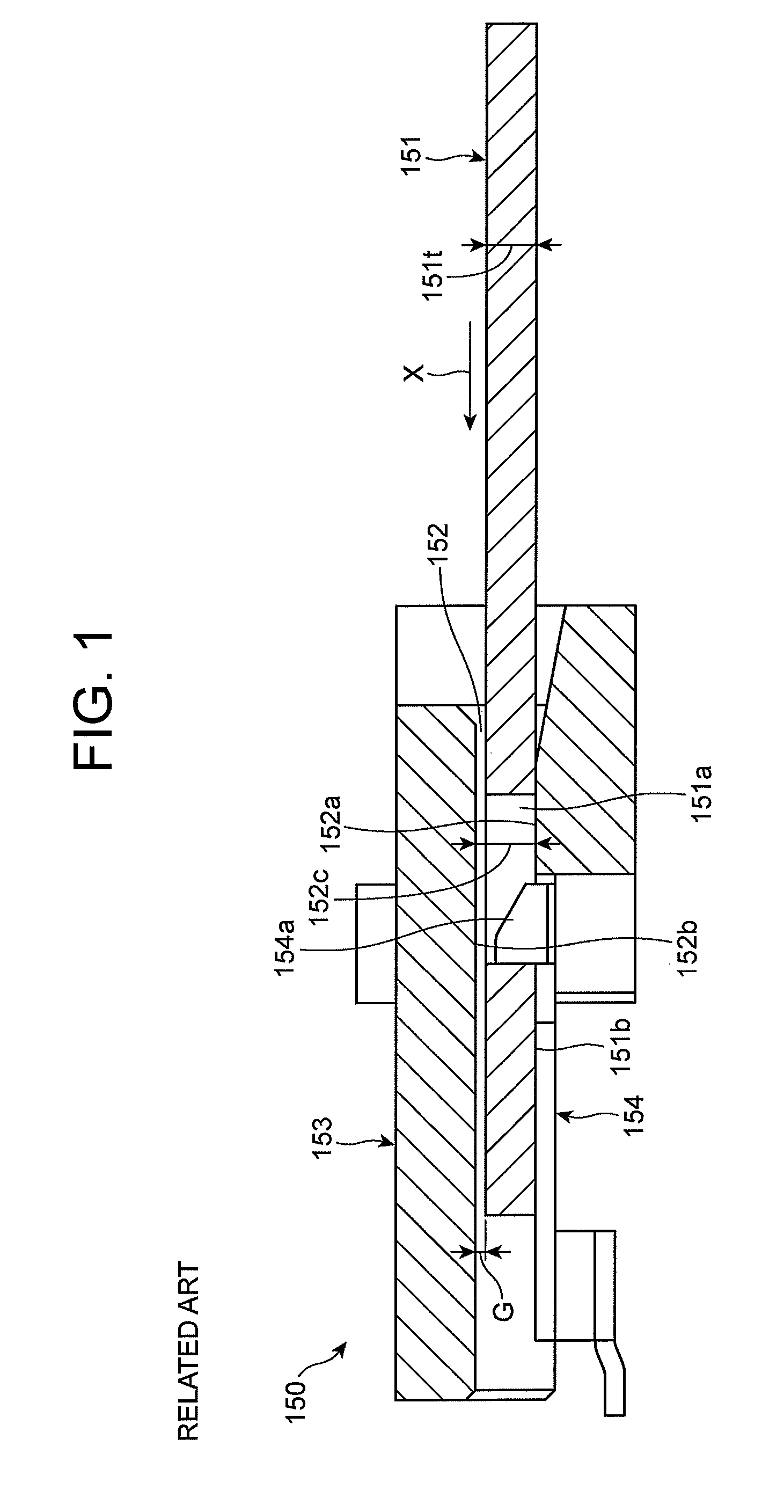
a technology of electric connectors and connectors, which is applied in the direction of electrical apparatus, connection, coupling device connection, etc., can solve the problems of reducing the reliability of contact in the conventional electric connectors illustrated in fig. 1 and cannot be prevented by the above-identified publication, and achieves the effect of high reliability of electric connection

Inactive Publication Date: 2015-03-03
DAIICHI SEIKO CO LTD
View PDF21 Cites 16 Cited by
  • Summary
  • Abstract
  • Description
  • Claims
  • Application Information

AI Technical Summary

Benefits of technology

[0011]In view of the above-mentioned problem in the conventional electric connector, it is an object of the present invention to provide an electric connector capable of presenting highly reliable electric connection between an electric connector and a signal-transmission medium, even if there were a variance in a thickness of the signal-transmission medium.
[0013]In the electric connector in accordance with the present invention, when a signal-transmission medium having been inserted into the groove of the housing is fixed by means of the locker, the compressor of the lock device compresses the signal-transmission medium towards the second inner surface, ensuring that no gap is formed between the signal-transmission medium and the second inner surface of the groove, and hence, a length by which the locker is engaged to a cut-out of the signal-transmission medium can be constant. Thus, even if there were a variance in a thickness of a signal-transmission medium, highly reliable electric connection can be presented between an electric connector and a signal-transmission medium.
[0017]It is preferable that the lock device further includes a releaser for, when compressed, causing the lock device to be elastically deformed to thereby cause the locker to be released from the signal-transmission medium.
[0022]By so designing the lock device, it is possible to provide a function of surely locking a signal-transmission medium and a function of compressing the same regardless of a simple structure of the lock device, ensuring enhanced contact reliability between the electric connector and a signal-transmission medium.
[0031]The electric connector in accordance with the present invention is capable of presenting highly reliable electric connection between itself and a signal-transmission medium, even if there were a variance in a thickness of a signal-transmission medium.

Problems solved by technology

Though the “connector” suggested in the above-identified Publication is designed to have a countermeasure for avoiding the reduction in contact reliability, the reduction in contact reliability in the conventional electric connector 150 illustrated in FIG. 1 cannot be prevented by the above-identified Publication.

Method used


Image

  • Electric connector
  • Electric connector
  • Electric connector

Examples


Embodiment Construction

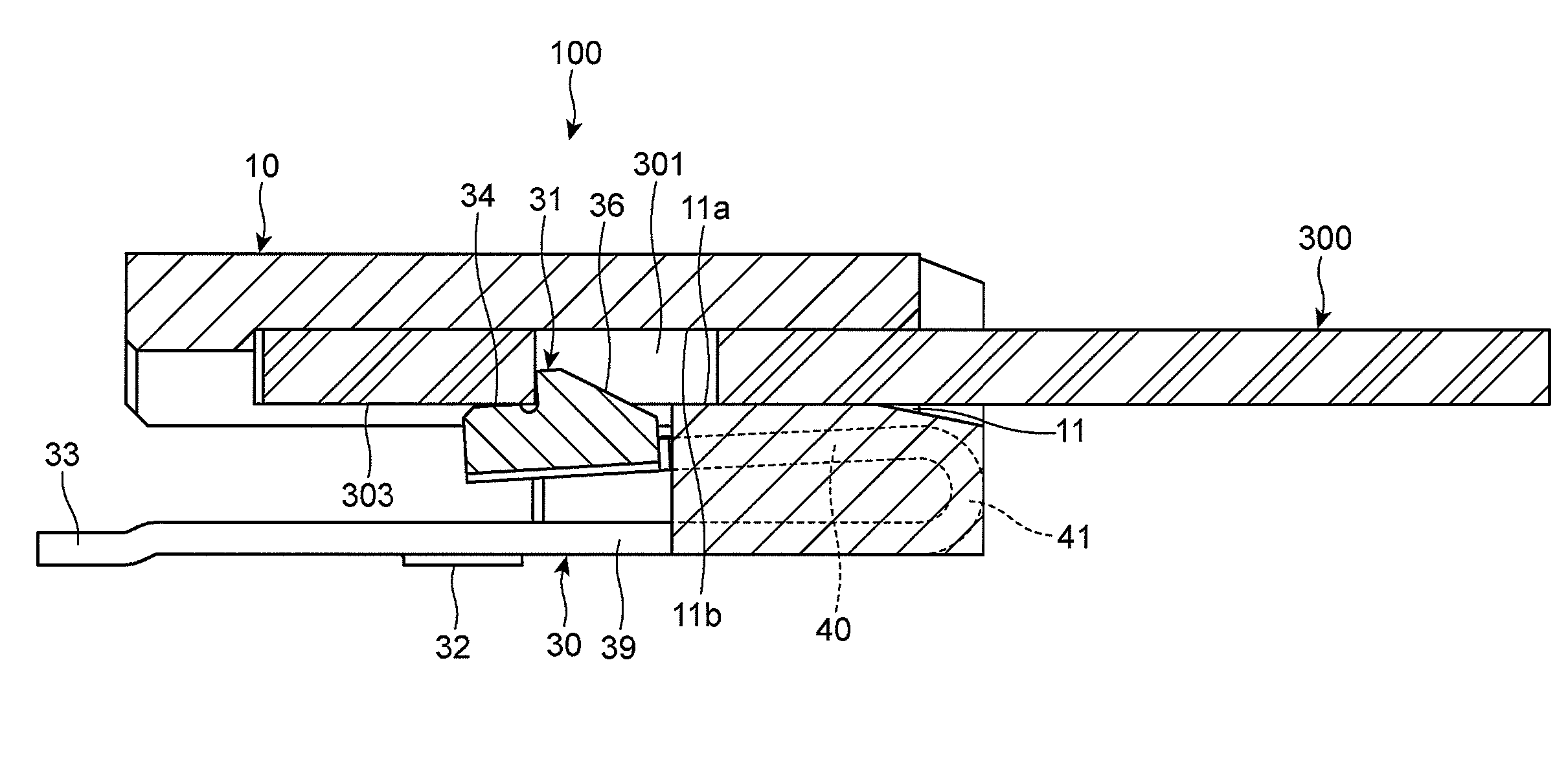
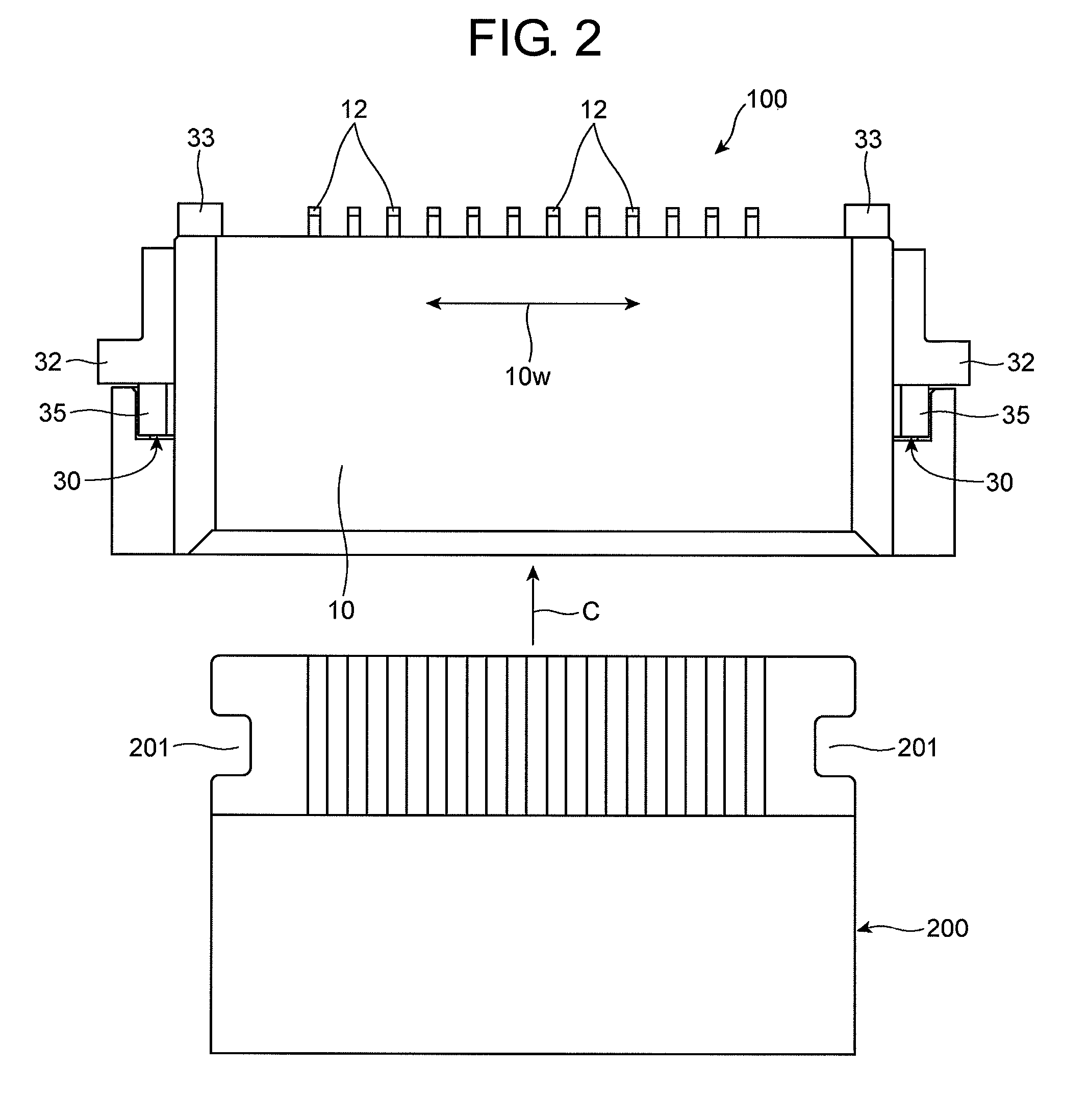
[0048]The electric connector in accordance with the preferred embodiment of the present invention is described hereinbelow with reference to FIGS. 2 to 15.

[0049]As illustrated in FIGS. 2 to 6, the electric connector 100 in accordance with the preferred embodiment of the present invention includes an electrically insulative housing 10 having a groove 11 into which a signal-transmission medium 200 is inserted at opposite edges thereof, and a lock device 30 including a locker 31 for locking the signal-transmission medium 200 at the groove 11 and allowing the signal-transmission medium 200 to be released out of the groove 11. The locker 31 is designed to move up beyond and move down below a lower inner surface 11a of the groove 11 extending in parallel with a direction C in which the signal-transmission 200 is inserted into the groove 11, and is energized towards an upper inner surface 11b of the groove 11 situated facing the lower inner surface 11a. The lock device 30 further includes ...


PUM


Abstract

An electric connector includes a housing having a groove configured to receive a signal-transmission medium, and a lock device including a locker configured to lock the signal-transmission medium at the groove, the locker being configured to move up beyond and down below a first inner surface of the groove extending in parallel with a direction in which the signal-transmission medium is received in the groove, the locker being energized towards a second inner surface of the groove, the second inner surface being disposed opposite to the first inner surface, and the lock device further including a compressor configured to compress the signal-transmission medium towards the second inner surface.

Description

BACKGROUND OF THE INVENTION[0001]1. Field of the Invention[0002]The invention relates to an electric connector to be equipped in a circuit board and used for electrically connecting to a signal-transmission medium such as FPC (Flexible Printed Circuit) and FFC (Flexible Flat Cable). The invention further relates to a lock device to be used in an electric connector.[0003]2. Description of the Related Art[0004]FIG. 1 is a cross-sectional view of a conventional electric connector used for electrically connecting to a signal-transmission medium such as FPC and FFC.[0005]As illustrated in FIG. 1, the conventional electric connector 150 includes a housing 153 having a groove 152 into which a signal-transmission medium 151 such as FPC and FFC is inserted at opposite edges thereof, and a lock device 154 including a lock 154a for locking the signal-transmission medium 151 at the groove 152 and allowing the signal-transmission medium 151 to be released out of the groove 152. The locker 154a i...

Claims


Application Information

Patent Timeline
Patent Type & Authority Patents(United States)
IPC IPC(8): H01R12/79H01R12/77H01R12/87H01R13/627
CPCH01R13/627H01R12/774H01R12/79H01R13/6275H01R12/87
Inventor NISHIYAMA, KOHEI
Owner DAIICHI SEIKO CO LTD
Why Eureka
Try Eureka