Image combining system, device, and method of multiple vision sources

a technology of image combining and visual sources, applied in the field of display systems, can solve problems such as the inability to display actual objects in the scene in front of the aircra

Active Publication Date: 2015-03-10
ROCKWELL COLLINS INC
View PDF1 Cites 19 Cited by
  • Summary
  • Abstract
  • Description
  • Claims
  • Application Information

AI Technical Summary

Benefits of technology

[0010]In another embodiment, a method for combining image data is disclosed. The method may be comprised of receiving a first image data set; receiving a depth buffer data set; receiving a second image data set; generating a third image data set as a function of the first image data set, the depth buffer data set; the second image data set, and data representative of a pixel cutoff distance; and providing the third image data set to one or more user systems. As embodied herein, at least one depth distance of the depth buffer data set could be determined as a function of the pixel cutoff distance and a surface feature. In addition, the ...

Problems solved by technology

One of the advantages of the SVS is that the image is not affected by meteorological conditions; however, o...

Method used


Image

  • Image combining system, device, and method of multiple vision sources
  • Image combining system, device, and method of multiple vision sources
  • Image combining system, device, and method of multiple vision sources

Examples


Embodiment Construction

[0017]In the following description, several specific details are presented to provide a thorough understanding of embodiments of the invention. One skilled in the relevant art will recognize, however, that the invention can be practiced without one or more of the specific details, or in combination with other components, etc. In other instances, well-known implementations or operations are not shown or described in detail to avoid obscuring aspects of various embodiments of the invention.

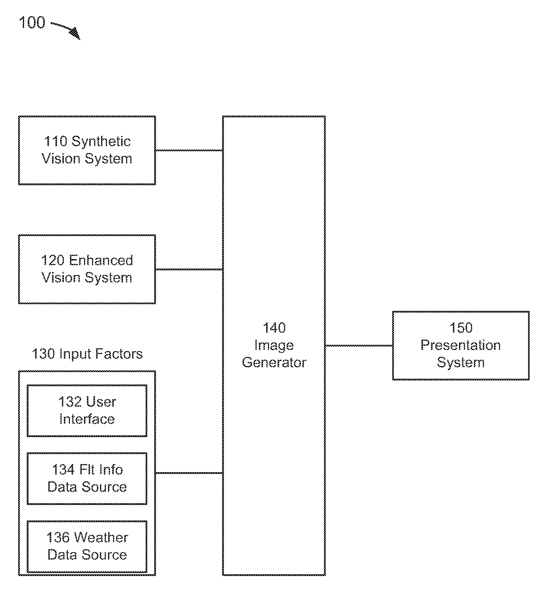
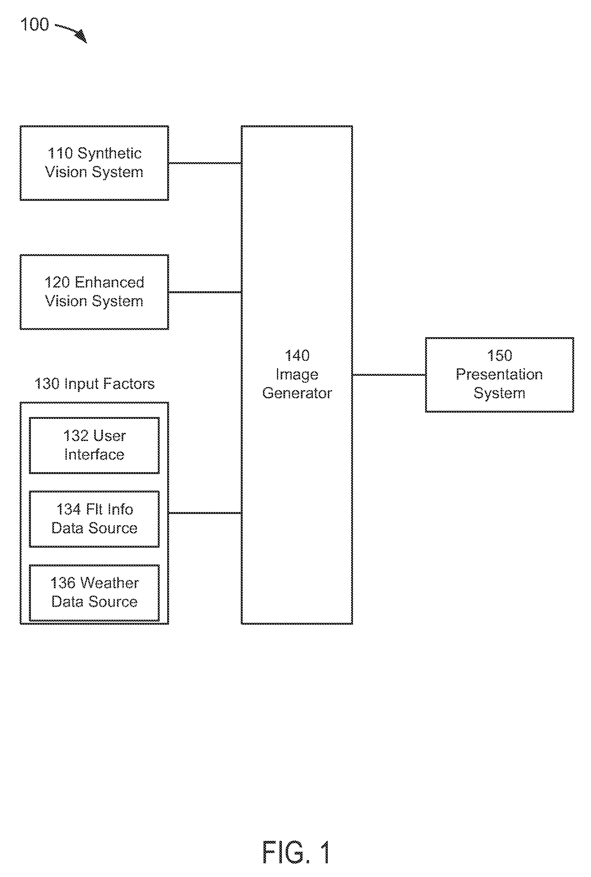
[0018]FIG. 1 depicts a functional block diagram of a combined vision system 100 suitable for implementation of the techniques described herein. The functional blocks of the system may include a synthetic vision system (“SVS”) 110, an enhanced vision system (“EVS”) 120, an input variable system(s) 130, an image generator (“IG”) 140, and a presentation system 150.

[0019]In an embodiment of FIG. 1, the SVS 110 could be comprised of any system which generates data representative of the synthetic image, w...


PUM


Abstract

Present novel and non-trivial system, device, and method for combining image data received from two or more vision systems are disclosed. A system may be comprised of a first vision source, a second vision source, and an image generator (“IG”). The first vision source may be could configured to generate a first image data set and a depth buffer data set, and the second vision data source could configured to generate a second image data set. The IG could be configured to receive both the first and second image data sets; the depth buffer data set; and generate a third image data set as a function of both image data sets, the depth buffer data set, and a pixel cutoff distance that may be fixed or variable. In addition, the pixel cutoff distance may be determined as a function of input variable data.

Description

BACKGROUND OF THE INVENTION[0001]1. Field of the Invention[0002]This invention pertains generally to the field of display systems such as, but not limited to, aircraft display systems.[0003]2. Description of the Related Art[0004]Two vision systems employed commonly in the aviation industry are the synthetic vision system (“SVS”) and the enhanced vision system (“EVS”). The SVS typically employs a terrain database to create a three-dimensional perspective of the scene in front of the aircraft on a two-dimensional display unit, whereas the EVS typically employs image sensor(s) to acquire real-world image data representative of an image that may be presented on the screen of one or more display units. Each vision system has its advantages and its disadvantages. One of the advantages of the SVS is that the image is not affected by meteorological conditions; however, one of its disadvantages is its inability to display actual objects location in the scene in front of the aircraft.[0005]Th...

Claims


Application Information

Patent Timeline
IPC IPC(8): G08B21/00G06F7/70G01C21/00
CPCG01C23/00G06T15/405G06T19/20G06T2219/2024G08G5/0021G09G2340/12G09G2380/12
Inventor CHIEW, DANIEL Y.YUM, ROGER L.VANDERKAMP, TRAVIS S.REID, ALEXANDER D.TIANA, CARLO L.LAHR, WESTON J.
Owner ROCKWELL COLLINS INC
Why Eureka
Try Eureka