Stand-alone interbody fixation system

a technology of interbody fixation and spinal cord, applied in the field of spinal orthopedics, can solve the problems of chronic and/or debilitating back pain, irritated nerves passing near the affected area, and affecting the function of spinal cord, and achieve the effect of less invasive approach

Active Publication Date: 2015-03-17
ALPHATEC SPINE INC
View PDF2 Cites 3 Cited by
  • Summary
  • Abstract
  • Description
  • Claims
  • Application Information

AI Technical Summary

Benefits of technology

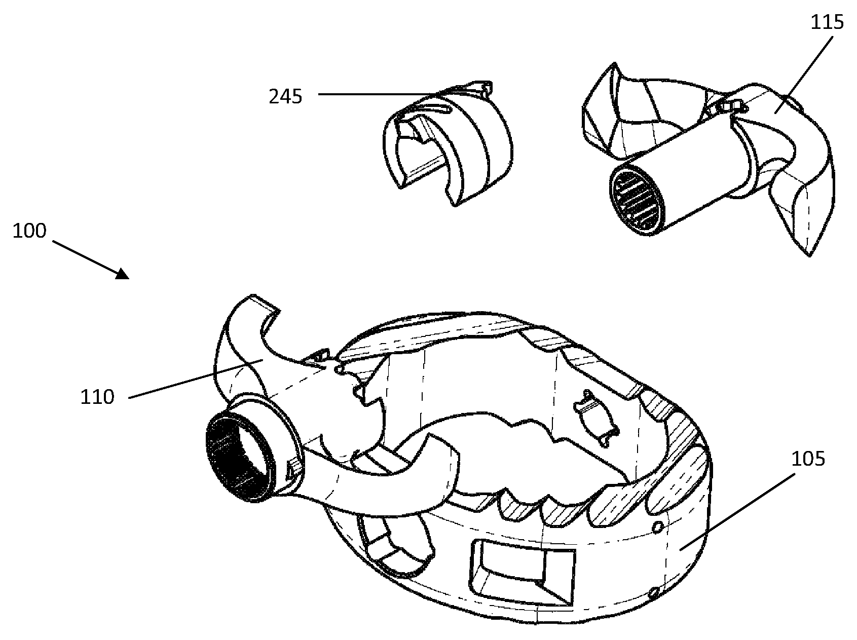
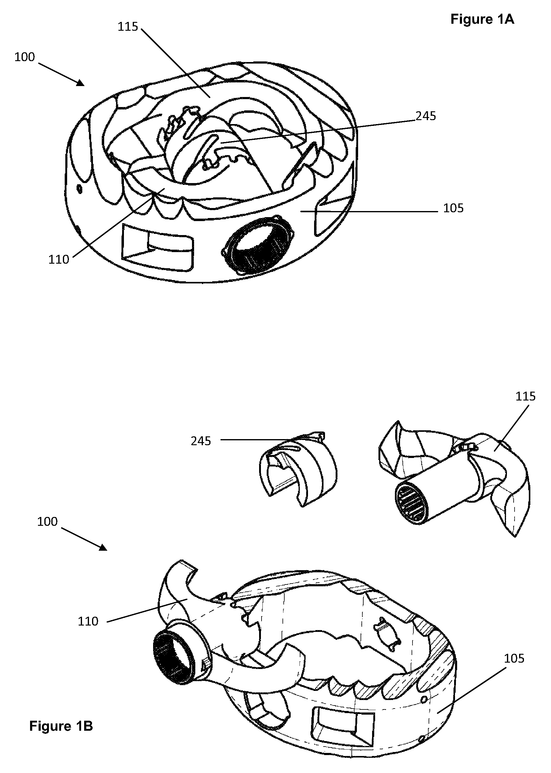
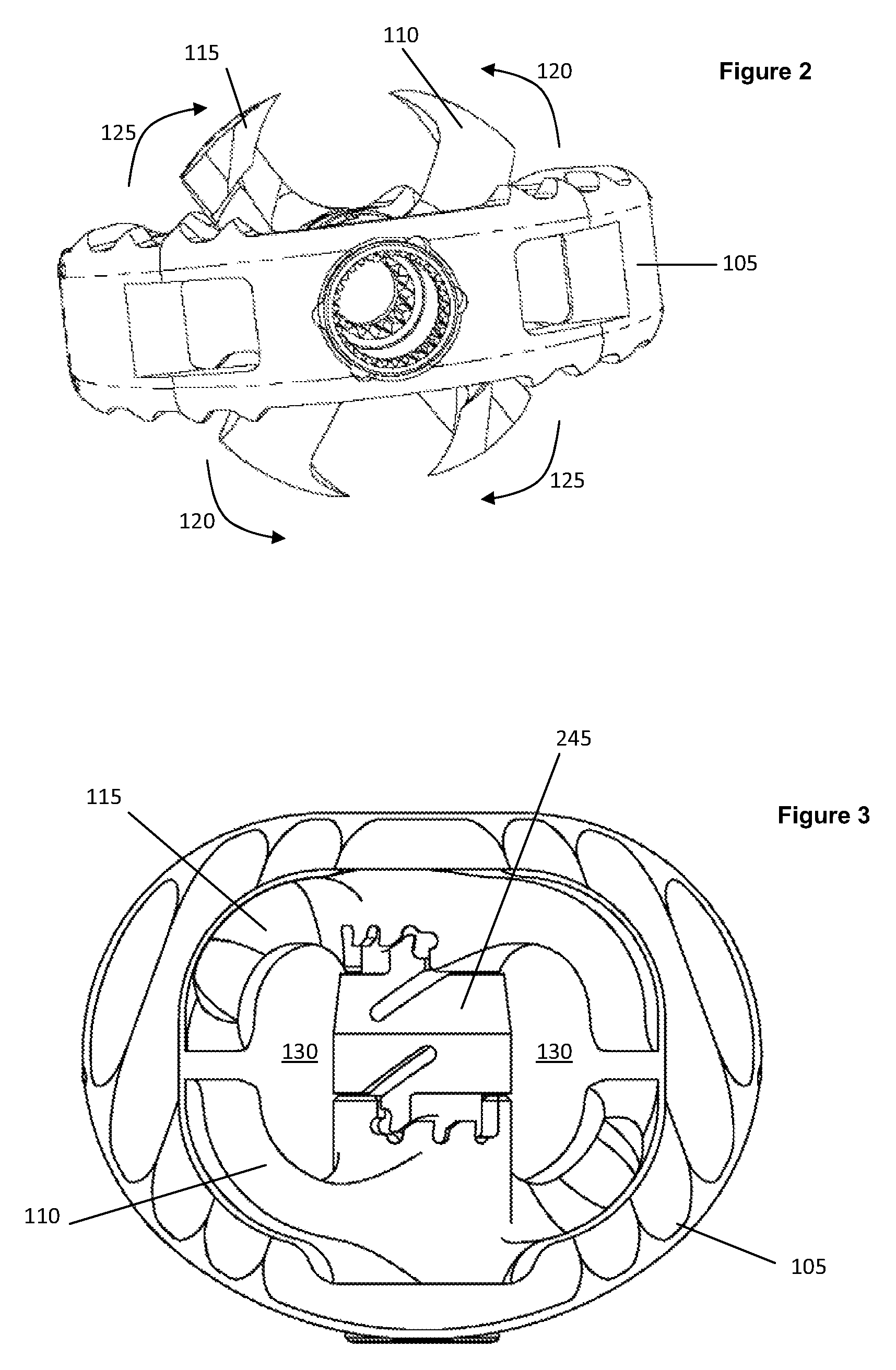
[0008]Generally, embodiments of the present invention provide a stand-alone single fixation system having a cage, an anterior fixation blade and a posterior fixation blade. The anterior and posterior blades may be positioned within the cage in a delivery position and rotated from the cage to a deployed position. A ratcheting mechanism is provided which engages with the blades to lock the blades in position as they are deployed. The stand-alone interbody fixation system is a pre-assembled multi-component design which integrates a fixation feature with an interbody spacer, no additional support is required. The system may be used in spinal fusion surgeries including ALIF, PLIF and TLIF procedures, wherein two or more vertebrae are joined or fused together for the treatment of spinal disorders such as spondylolisthesis, scoliosis, severe disc degeneration, or spinal fractures. The system may also be used in open and minimally invasive surgery (MIS) procedures, and using low profile instrumentation facilitates a less invasive approach through a smaller incision.

Problems solved by technology

When one or more disks degenerate through accident or disease, nerves passing near the affected area may be compressed and are consequently irritated.
The result may be chronic and / or debilitating back pain.
One significant challenge to providing fusion stability (prior to actual bone ingrowth fusion) is preventing spinal extension during patient movement.
Distraction of the vertebral space containing the fusion graft may cause the interbody spacer to shift or move disrupting bone ingrowth fusion and causing pain.

Method used


Image

  • Stand-alone interbody fixation system
  • Stand-alone interbody fixation system
  • Stand-alone interbody fixation system

Examples


Embodiment Construction

[0041]The foregoing and other features and advantages of the invention are apparent from the following detailed description of exemplary embodiments, read in conjunction with the accompanying drawings. The detailed description and drawings are merely illustrative of the invention rather than limiting, the scope of the invention being defined by the appended claims and equivalents thereof.

[0042]Embodiments of the invention will now be described with reference to the Figures, wherein like numerals reflect like elements throughout. The terminology used in the description presented herein is not intended to be interpreted in any limited or restrictive way, simply because it is being utilized in conjunction with detailed description of certain specific embodiments of the invention. Furthermore, embodiments of the invention may include several novel features, no single one of which is solely responsible for its desirable attributes or which is essential to practicing the invention describ...


PUM


Abstract

A stand-alone interbody fixation system having a cage, anterior fixation blade and posterior fixation blade. The cage includes an annular side wall with an open interior and upper and lower surfaces, the cage being configured to fit between end plates of adjacent vertebrae. The anterior fixation blade includes an anterior alignment boss with two opposing outward extending anterior blades with end plate penetrating tips configured to fit within the open interior of the cage. The posterior fixation blade includes a posterior alignment boss with two opposing outward extending posterior blades with end plate penetrating tips configured to fit within the open interior of the cage. The anterior and posterior fixation blades are counter-rotating blades and the anterior alignment boss and posterior alignment boss are configured to receive or engage a deployment instrument having an anterior engagement portion and a posterior engagement portion configured to rotate the anterior and posterior fixation blades from a stowed position to a deployed condition.

Description

CROSS-REFERENCES TO RELATED APPLICATIONS[0001]The present application is a continuation-in-part of U.S. patent application Ser. No. 12 / 852,033, filed Aug. 6, 2010, which claims priority from U.S. Provisional Application No. 61 / 231,967, which was filed on Aug. 6, 2009, both of which are incorporated herein by reference in their entirety.BACKGROUND[0002]The present invention generally relates to the field of spinal orthopedics, and more particularly to methods and systems for securing interbody cages within the intervertebral space.[0003]The spine is a flexible column formed of a plurality of bones called vertebra. The vertebrae are hollow and piled one upon the other, forming a strong hollow column for support of the cranium and trunk. The hollow core of the spine houses and protects the nerves of the spinal cord. The different vertebrae are connected to one another by means of articular processes and intervertebral, fibrocartilaginous bodies.[0004]The intervertebral fibro-cartilages...

Claims


Application Information

Patent Timeline
Patent Type & Authority Patents(United States)
IPC IPC(8): A61F2/44A61F2/30
CPCA61F2/442A61F2/4455A61F2002/30579A61F2002/3052A61F2002/30476
Inventor VISHNUBHOLTA, SRICHENG, YANGCASTILLO, LEOPOLDO
Owner ALPHATEC SPINE INC
Why Eureka
Try Eureka