Multi-step solvent extraction process for heavy oil reservoirs

a multi-step, heavy oil technology, applied in the field of hydrocarbon extraction, can solve the problems of limited solvent dilution rate into stranded oil on a reservoir wide basis, extremely slow initial penetration of solvent into oil, etc., and achieve the effect of rapid dilution of partly diluted oil, effective and predictable mobilization

Inactive Publication Date: 2015-03-24
N SOLV CORP
View PDF78 Cites 5 Cited by
  • Summary
  • Abstract
  • Description
  • Claims
  • Application Information

AI Technical Summary

Benefits of technology

[0013]The initial penetration of solvent into oil is now understood to be extremely slow. On the other hand, as soon as a small amount of solvent perhaps only one or two percent, has diffused into the oil held within in a particular pore, in a pay zone, the subsequent dilution of the partly diluted oil is very rapid. This results in a distinct solvent / diluted oil to heavy oil interface that advances slowly across the pay zone of a reservoir, on a pore by pore basis. The present invention teaches a method and process which comprehends this slow solvent front propagation and consequently has an objective of allowing effective and predictable mobilization and recovery of large volumes of stranded in situ heavy oil.
[0014]The present invention recognizes how difficult it is to achieve uniform dispersal of the solvent within the pay zone of the heavy oil reservoir and provides certain process steps to encourage solvent dilution and homogeneity. The presence of the shallow penetration and steep concentration gradient at the shock front means that the rate of solvent dilution into the stranded oil on a reservoir wide basis is limited by two key variables, namely the amount of stranded oil interfacial area available to the solvent and the amount of time the solvent is exposed to the interfacial area of the stranded oil. The degree of solvent dilution into the heavy oil determines the change in viscosity of the solvent oil blend, which in turn is directly related to the mobility of the heavy oil blend in the reservoir and the ability to recover the same through gravity drainage from a production well.
[0015]According to the present invention a process which maximizes the opportunity for dilution of the heavy oil with solvent will maximize the opportunities for recovery of the stranded heavy oil.
[0016]The present invention therefore consists of a procedure having several steps, including, increasing the interfacial area by removing solvent blockers from the voids created in the reservoir by the primary extraction process. Clearing out the voids allows more solvent to be placed in the reservoir permitting more solvent to contact more stranded oil thereby enabling the extraction process to proceed at much higher rates than would be possible in a virgin reservoir or even a partially extracted reservoir having voids filled with solvent blocking reservoir fluids and gases. Furthermore this invention comprehends providing enough exposure time for the solvent and oil in a ripening step to permit the solvent to slowly but adequately penetrate into oil filled pores and achieve a reasonable degree of homogeneity or dissolution at a micro scale level, throughout the reservoir. According to an aspect of the present invention the degree of in situ ripening is measurable to permit a determination of when to proceed to the next step of the extraction process, which is the actual production of the oil from the reservoir, through gravity drainage.
[0020]c. Shutting in said reservoir for a sufficient period of time to permit said solvent to diffuse into said unextracted oil across said interfacial area in a ripening step to create a reduced viscosity blend of solvent and oil;

Problems solved by technology

The initial penetration of solvent into oil is now understood to be extremely slow.
The presence of the shallow penetration and steep concentration gradient at the shock front means that the rate of solvent dilution into the stranded oil on a reservoir wide basis is limited by two key variables, namely the amount of stranded oil interfacial area available to the solvent and the amount of time the solvent is exposed to the interfacial area of the stranded oil.

Method used


Image

  • Multi-step solvent extraction process for heavy oil reservoirs
  • Multi-step solvent extraction process for heavy oil reservoirs
  • Multi-step solvent extraction process for heavy oil reservoirs

Examples


Embodiment Construction

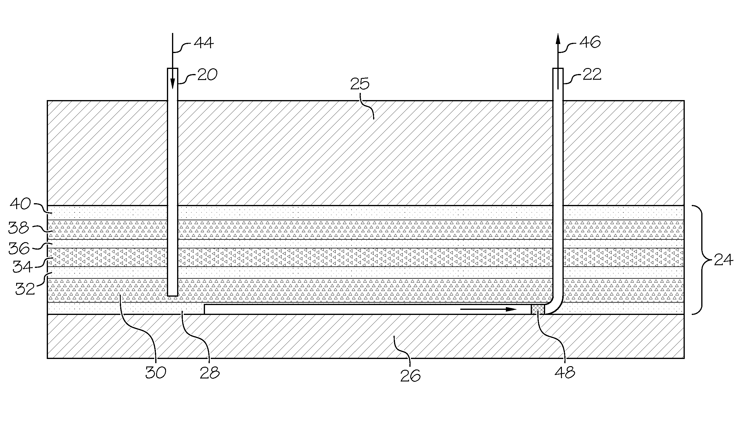
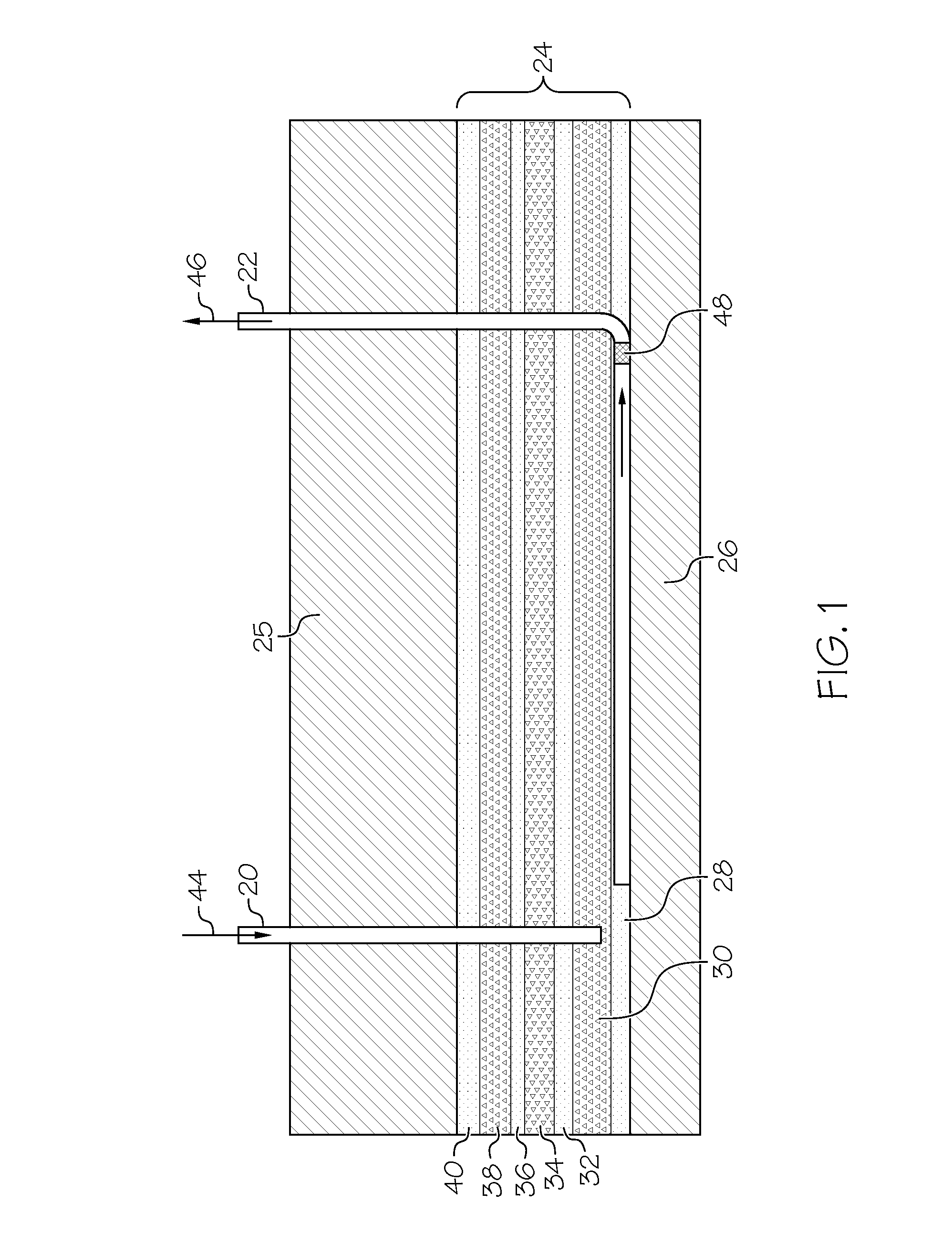
[0035]This present invention is most applicable to heavy oil reservoirs which have undergone a primary extraction and also which demonstrate good confinement. According to the present invention the primary extraction has resulted in an oil extracted region in the reservoir having either gas or water filled voids. A preferred reservoir has had a primary extraction which has recovered between about 5% and 25% of the original oil in place with a most preferred amount being between 8% and 15%. Most preferably a suitable target reservoir will have a significant pay thickness without extensive horizontal barriers so that when the viscosity of the in situ heavy oil is sufficiently reduced, gravity drainage can occur. While a primary extracted reservoir is preferred the present invention is also suitable for virgin reservoirs of the type having naturally occurring drainable voids having a volume of between about 5% and 25% of the original oil in place. An example of such a reservoir is one ...


PUM


Abstract

An in situ extraction process for heavy oil reservoirs using solvent comprises removing liquids and gases from areas contacting with the heavy oils to increase an interfacial area of unextracted heavy oil contactable by the solvent. Solvent vapor is injected into the areas to raise the reservoir pressure until sufficient liquid solvent is present to contact the increased interfacial area. The reservoir is shut in for a sufficient time for the solvent to diffuse into the unextracted oil across the interfacial area in a ripening step to create a reduced viscosity blend of solvent and oil. One or more reservoir characteristics is measured to confirm the extent of solvent dilution that has occurred of the unextracted oil in the reservoir. Gravity drainage based production is commenced from the reservoir upon the blend having a viscosity low enough to permit the blend to drain through the reservoir to a production well.

Description

FIELD OF THE INVENTION[0001]This invention relates to the field of hydrocarbon extraction and more particularly to the extraction of heavy oil from underground formations. Particularly, this invention relates to a multi-step heavy oil extraction technique to be used, for example, after primary extraction is no longer effective. Most particularly this invention relates to a solvent based multi-step enhanced extraction process for heavy oil.BACKGROUND OF THE INVENTION[0002]Heavy oil is a loosely defined term, but heavy oil is generally understood to comprehend somewhat degraded and viscous oils that may include some bitumen. Heavy oils typically have poor mobility at reservoir conditions so are hard to produce and have very poor recovery factors. Heavy oil is generally more viscous than light or conventional oil, but not as viscous as bitumen such as may be found in the oil sands. Heavy oil is generally understood to include a range of API gravity of between about 10 and 22 with a vis...

Claims


Application Information

Patent Timeline
Patent Type & Authority Patents(United States)
IPC IPC(8): E21B43/16E21B47/06
CPCE21B43/16E21B43/168
Inventor NENNIGER, JOHN
Owner N SOLV CORP
Why Eureka
Try Eureka