Aircraft light for emitting light in a desired spatial angular region and with a desired light distribution

a technology of spatial angular region and aircraft light, which is applied in the direction of portable electric lighting, lighting and heating equipment, lighting and heating arrangements, etc., can solve the problems of increasing costs and inability to easily combine position light functionality, and achieves the effect of reducing costs, wide spread, and without significant losses

Inactive Publication Date: 2015-03-24
GOODRICH LIGHTING SYST GMBH
View PDF8 Cites 2 Cited by
  • Summary
  • Abstract
  • Description
  • Claims
  • Application Information

AI Technical Summary

Benefits of technology

[0017]The present invention allows for a very compact, efficient, wide spread and thermally robust strobe light at reduced cost. It is especially well suited for the tail strobe light of an aircraft and with a curved aerodynamic lens (also referred to as cover) and does not require any optical elements in the lens. According to the invention, it is also possible to implement the permanent illuminated tail position light functionality into the aircraft light without any major further optical design work. A few of the LEDs (e.g. about 10%) of the aircraft light would then be kept on permanently, while the other LEDs are flashing to fulfill the strobe light functionality.
[0018]The aircraft light according to the invention is based on the concept of having a large optical system to create the peaks within the required light distribution with the aid of the first LEDs facing in the opposite direction of the main illumination action (desired spatial angular region) wherein the reflector is used to direct the light emitted by the second LEDs towards the main illumination action direction, namely towards the desired spatial angular region. The majority of the LEDs of the aircraft according to the invention, namely the first LEDs, are facing towards the desired spatial angular region and emit their light without any significant losses due to an optical system or the like.
[0019]Additionally, the curved cover or lens which can be used in the aircraft light according to the invention allows for the light to pass through the cover perpendicularly for the most part of the light rays, allowing for minimal transmission losses. The cover or lens suitable for the present invention can be designed so that no light rays of the LEDs are passing through the cover at more than 50 degrees in the vertical axis. Merely two carrier elements are necessary, with the one carrier element carrying the first LEDs and the other carrier element carrying the second LEDs. Some of the LEDs (some of the first and / or some of the second LEDs) can be operated permanently for providing the navigation light functionality while the others (namely the majority) of the first and second LEDs are flashing performing the strobe light functionality.
[0020]The structure of the aircraft light according to the invention can be described as an individually controllable double-string of LEDs emitting their light in opposite directions. A relatively large optical system is used in the aircraft light according to the invention which comprises the reflector in rearward direction for creating a peak of the desired light distribution within the desired spatial angular region. The highly efficient wide-spread illumination required according to the desired light distribution is created by the LEDs directly facing into the desired spatial angular region in conjunction with the curved lens, minimizing transmission losses as explained above. The light rays of the LEDs for the most part are passing perpendicular through the lens or light cover. Individually controllable LEDs allow for an integration of a strobe and a position light function in the same housing.

Problems solved by technology

Most often strobe lights and aircraft position lights are separated from each other which means additional mechanical and electrical expenditures which results in increased costs.
Most of the known designs use optics for each LED and cannot easily be combined with a position light functionality.

Method used


Image

  • Aircraft light for emitting light in a desired spatial angular region and with a desired light distribution
  • Aircraft light for emitting light in a desired spatial angular region and with a desired light distribution
  • Aircraft light for emitting light in a desired spatial angular region and with a desired light distribution

Examples


Embodiment Construction

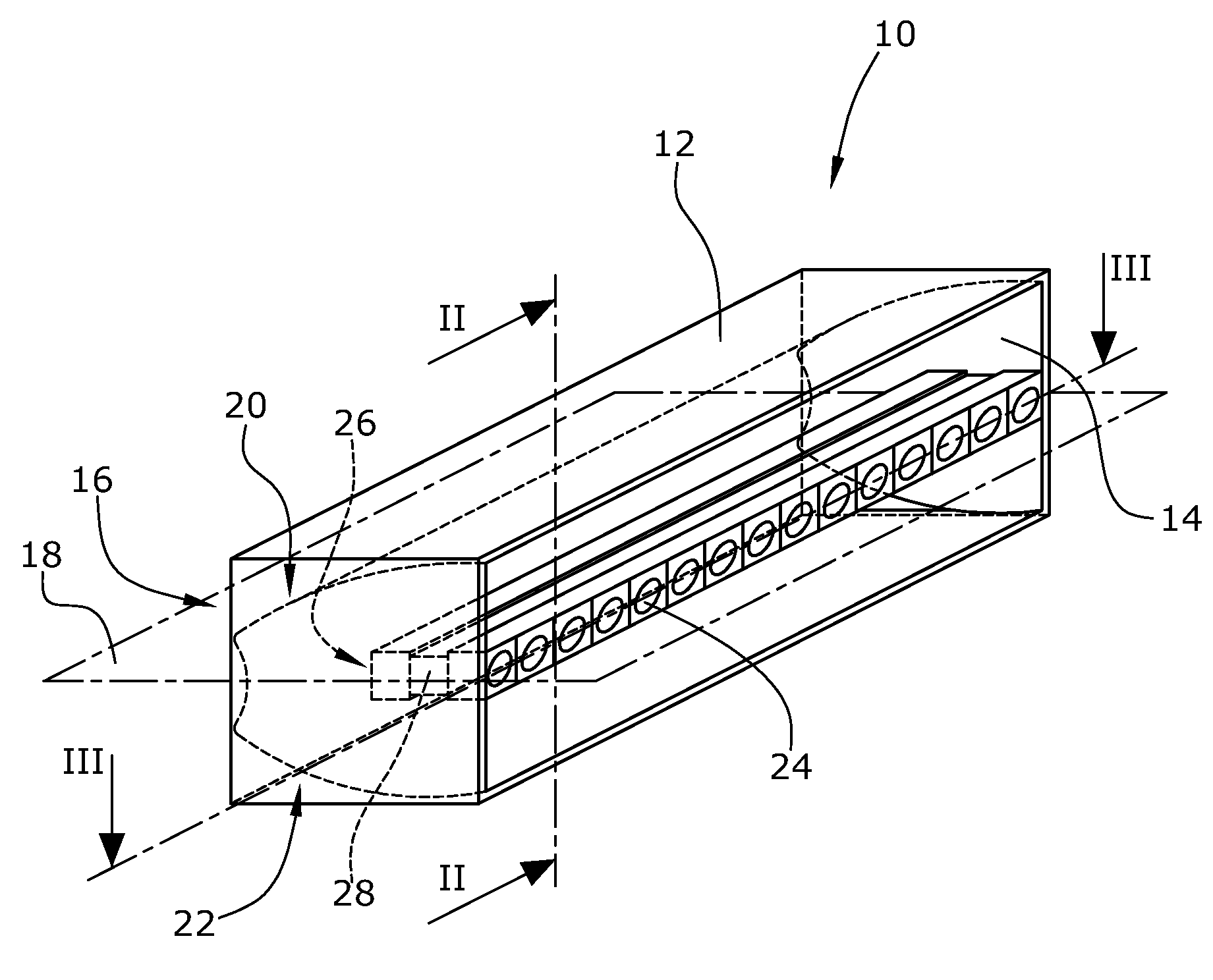
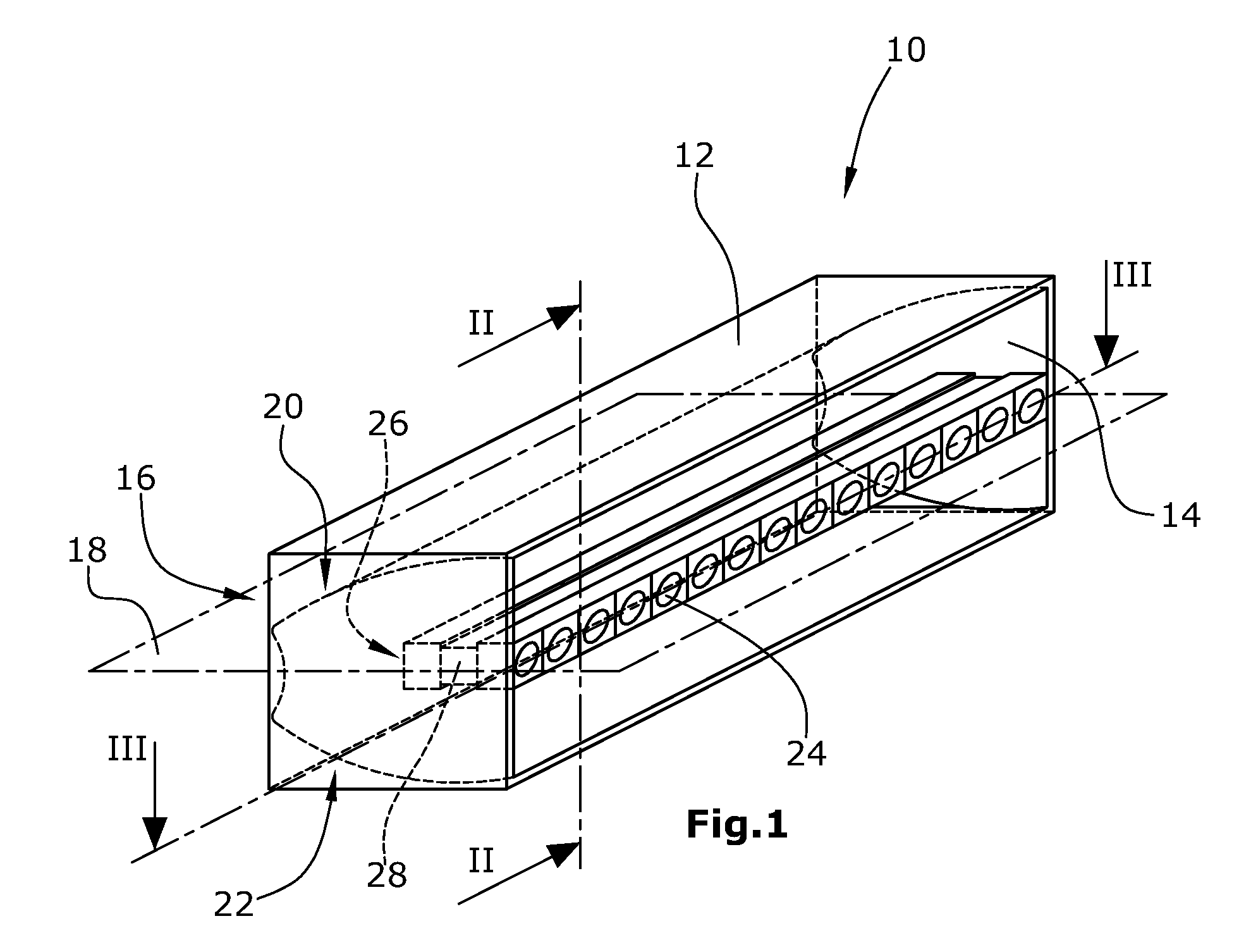
[0027]According to FIG. 1, an aircraft light 10 according to the invention comprises a longitudinal housing 12 having a front opening 14 and a reflector 16 arranged within the housing 12. The reflector 16 is symmetrical with respect to a plane 18 and comprises an upper reflector portion 20 and a lower reflector portion 22. In FIG. 1 the lens or cover by which the front opening 14 of the housing 12 is closed, is not shown.

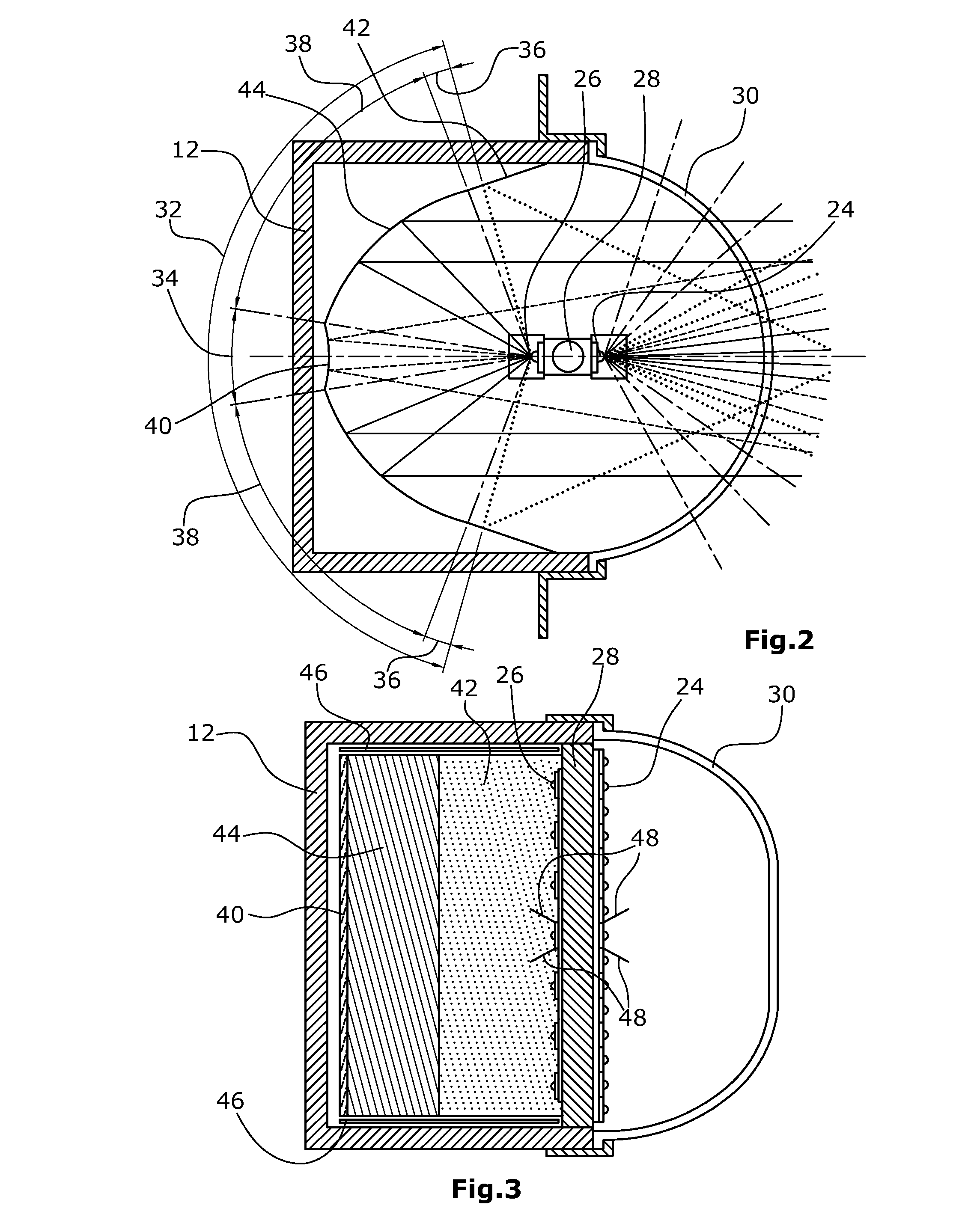
[0028]Within the housing 12 there is arranged a strip-like arrangement of LEDs facing in opposite directions. First LEDs 24 are arranged so as to emit light directly into a desired spatial angular region in front of the front opening 14. In other words, the first LEDs 24 are facing away from the reflector 16. The first LEDs 24 are arranged side by side along a single line, i.e. are arranged linearly within the plane 18. Second LEDs 26 are arranged so as to face away from the first LEDs and, accordingly, towards the reflector 16 so that their light is reflected by th...


PUM


Abstract

An aircraft light for emitting light in a desired spatial angular region and with a desired light distribution, comprises a reflector having an upper reflector portion and a lower reflector portion both being symmetrical to a plane. A first row of LEDs are face away from the reflector. A second row of LEDs face towards the reflector. Each of the upper and lower portions of the reflector comprises first, second, and third reflective surfaces with the first reflective surface being convexly shaped, the second reflective surface being substantially flat, and the third reflective surface being partially parabolically shaped.

Description

BACKGROUND OF THE INVENTION[0001]The present invention relates to an aircraft light for emitting light in a desired spatial angular region and with a desired light distribution. Accordingly, the aircraft light can be used in particular as a strobe light and as a combined strobe and position light, in particular as a combined strobe and position tail light.DESCRIPTION OF THE PRIOR ART[0002]External aircraft lights have to emit light in a desired spatial angular region and with a desired light distribution (both horizontally as well as vertically). This is true e.g. for a strobe tail light of an aircraft. In order to be able to fulfill the requirements when using LEDs instead of xenon light sources, it is necessary to arrange a plurality of LEDs facing into different directions in order to emit the light in the desired spatial angular region and with the desired light distributions. Most often strobe lights and aircraft position lights are separated from each other which means additio...

Claims


Application Information

Patent Timeline
Patent Type & Authority Patents(United States)
IPC IPC(8): B64D47/06F21V29/00
CPCB64D47/06F21V29/00B64D2203/00
Inventor HESSLING, ANDRE
Owner GOODRICH LIGHTING SYST GMBH
Why Eureka
Try Eureka