Imaging lens

a technology of imaging lens and lens body, which is applied in the field of imaging lens, can solve the problems of difficult to achieve both satisfactory aberration correction, and achieve the effects of easy shading phenomenon, satisfactory imaging performance, and easy miniaturization of imaging lens

Active Publication Date: 2015-03-24
TOKYO VISIONARY OPTICS CO LTD
View PDF2 Cites 14 Cited by
  • Summary
  • Abstract
  • Description
  • Claims
  • Application Information

AI Technical Summary

Benefits of technology

[0012]Therefore, it is possible to somewhat compress the total optical length while securing a certain imaging angle of view. In addition, according to the invention, the respective lenses of the third lens to the fifth lens have relatively weak refractive powers. Aberrations generated in the first lens and the second lens, which have strong refractive powers, are suitably corrected through those third to fifth lenses, which have weak refractive powers.
[0031]As described above, when the maximum sag is restrained within a certain range, the third lens and the fourth lens have substantially uniform thicknesses in an optical axis direction and have less curved shapes. According to such third lens and fourth lens, it is possible to restrain generation of aberrations of complicated shapes and to satisfactorily correct aberrations generated in the first lens and the second lens. In addition, it is also possible to decrease sensitivity to deterioration of image-forming performance due to de-centering (imperfect alignment), tilting, and the like, which occur upon production of the imaging lens, i.e., sensitivity to production errors.
[0032]Moreover, since the thicknesses in the optical axis direction are substantially uniform, it is possible to improve fabrication performance upon production and restrain the manufacturing cost of the imaging lens. Here, “sag” means a distance from a tangential plane of each surface, which is orthogonal to the optical axis, to the surface in a direction parallel to the optical axis.
[0034]When a ratio of the composite focal length of the third lens and the fourth lens to the focal length of the whole lens system is restrained within the range defined by the conditional expression (14), it is possible to more satisfactorily correct aberrations. When the value exceeds the upper limit “10.0”, the composite refractive power of the third lens and the fourth lens is relatively weak and it is difficult to restrain aberrations within preferred ranges in a balanced manner. On the other hand, when the value is below the lower limit “2.0”, the composite refractive power of the third lens and the fourth lens is relatively strong, so that it is advantageous for correcting a distortion, but the astigmatic difference increases and it is difficult to obtain satisfactory image-forming performance.
[0037]When the imaging lens satisfies the conditional expression (15), it is possible to keep the maximum exit angle of the off-axis light beam small while attaining miniaturization of the imaging lens. When the value exceeds the upper limit “2.0”, although it is easy to keep the maximum exit angle of the off-axis light beam small, it is difficult to attain miniaturization of the imaging lens. On the other hand, when the value is below the lower limit “0.3”, although it is advantageous for miniaturization of the imaging lens, a chromatic aberration is insufficiently corrected and it is difficult to obtain satisfactory imaging performance. In addition, the maximum exit angle of the off-axis light beam increases and thereby the shading phenomenon easily occurs.
[0038]According to the imaging lens of the invention, it is possible to attain both miniaturization of the imaging lens and satisfactory aberration correction, and to provide a small imaging lens with satisfactorily corrected aberrations.

Problems solved by technology

As the resolution of the imaging element has been increased, it is more difficult to achieve satisfactory performance only with the three-lens configuration.
Since the total length of the lens system is long, however, it is difficult to attain both miniaturization of the imaging lens and satisfactory aberration correction.

Method used


Image

  • Imaging lens
  • Imaging lens
  • Imaging lens

Examples


Embodiment Construction

[0057]Hereunder, referring to the accompanying drawings, preferred embodiments of the present invention will be fully described.

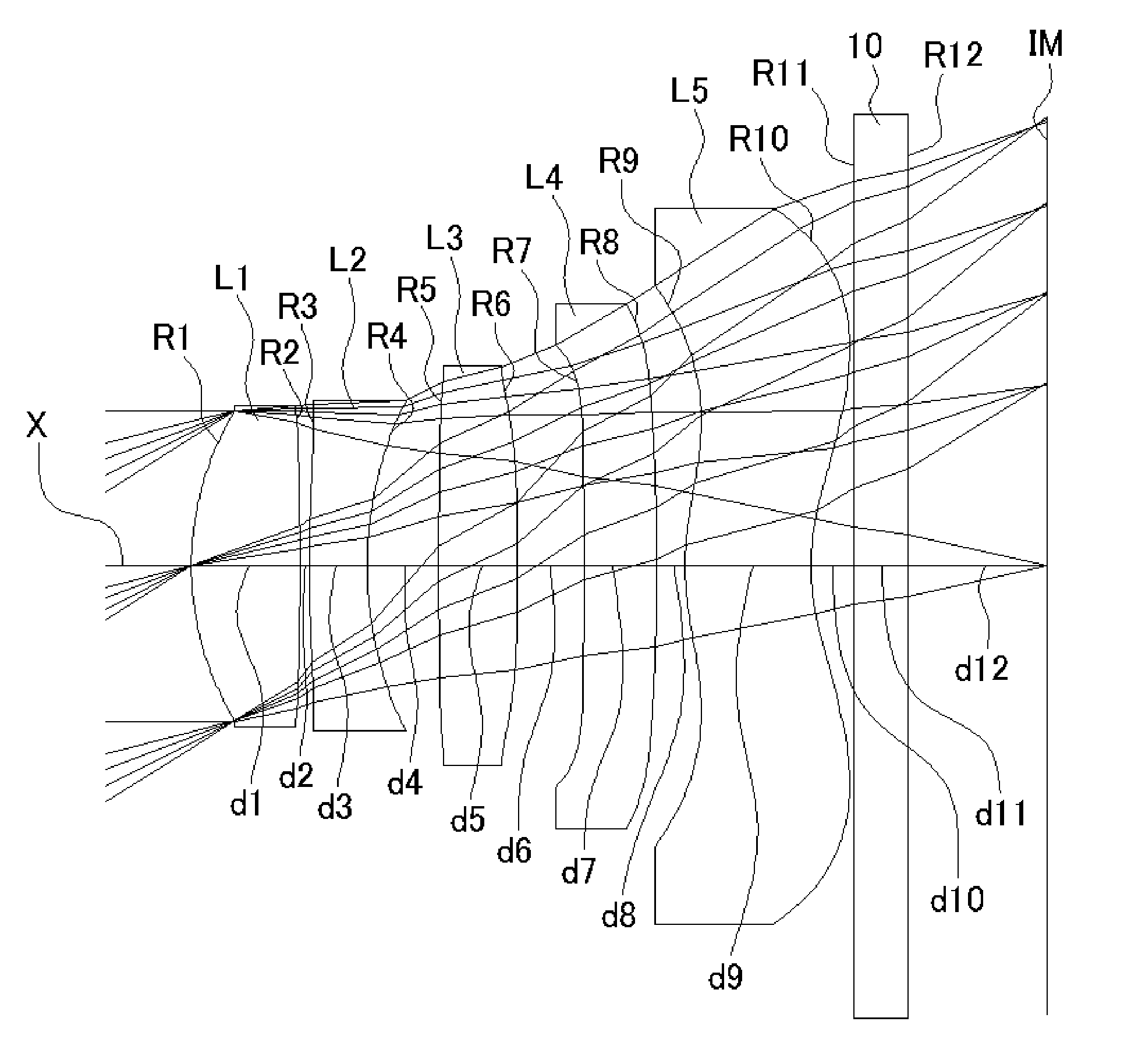
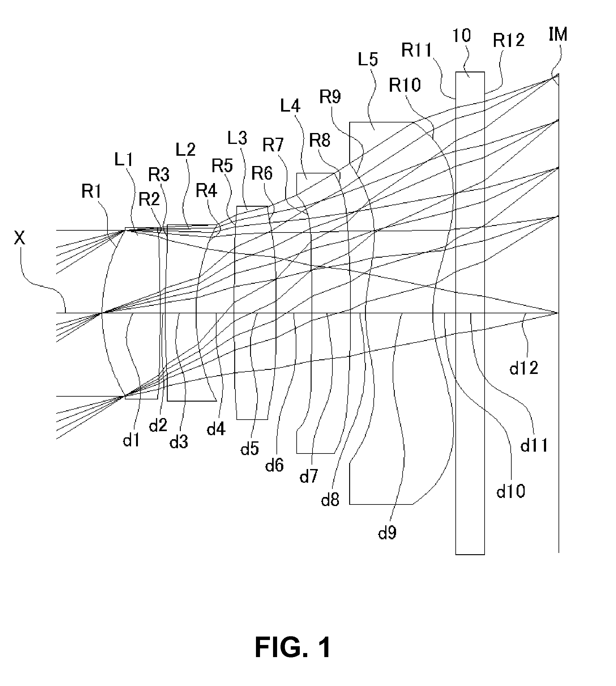
[0058]FIGS. 1, 4, 7, 10, 13, and 16 are sectional views of imaging lenses in Numerical Data Examples 1 to 6 according to the embodiment, respectively. Since a basic lens configuration is the same among the Numerical Data Examples, the lens configuration of the embodiment will be described with reference to the sectional view of Numerical Data Example 1.

[0059]As shown in FIG. 1, the imaging lens of this embodiment includes a first lens L1 having positive refractive power; a second lens L2 having negative refractive power; a third lens L3 having positive refractive power; a fourth lens L4 having negative refractive power; and a fifth lens L5 having negative refractive power, arranged in this order from an object side to an image plane side. A filter 10 such as an infrared cut-off filter and a cover glass is provided between the fifth lens L5 and the image pla...


PUM


Abstract

An imaging lens includes a positive first lens; a negative second lens with a meniscus lens shape directing a convex surface thereof to an object side near an optical axis; a positive third lens; a negative fourth lens with a meniscus lens shape directing a concave surface thereof to the object side near the optical axis; a negative fifth lens with a meniscus lens shape directing a convex surface thereof to the object side near the optical axis, arranged in this order from the object side. The imaging lens satisfies the following conditional expressions when the first lens has a focal length f1, the second lens has a focal length f2, the third lens has a focal length f3, the fourth lens has a focal length f4, and the fifth lens has a focal length f5: f1<f3and|f2|<f3f3<|f4|and|f2|<|f5|.

Description

BACKGROUND OF THE INVENTION AND RELATED ART STATEMENT[0001]The present invention relates to an imaging lens for forming an image on an imaging element such as a CCD sensor and a CMOS sensor. More specifically, the present invention relates to an imaging lens that is suitable for mounting on a relatively small camera such as a cellular phone, a digital still camera, a portable information terminal, a security camera, a vehicle onboard camera, and a network camera.[0002]An imaging lens for mounting on a small camera is required not only to be composed of a small number of lenses, but also to have a configuration that can attain high resolution, so as to be compatible with a high-resolution imaging element that has been available in recent years. Conventionally, a three-lens imaging lens configuration has been often used as such an imaging lens. As the resolution of the imaging element has been increased, it is more difficult to achieve satisfactory performance only with the three-lens...

Claims


Application Information

Patent Timeline
Patent Type & Authority Patents(United States)
IPC IPC(8): G02B9/60G02B13/00
CPCG02B13/0045G02B9/60G02B27/0025
Inventor KUBOTA, YOJIKUBOTA, KENICHIHIRANO, HITOSHIKURIHARA, ICHIROISE, YOSHIOYONEZAWA, TOMOHIRO
Owner TOKYO VISIONARY OPTICS CO LTD
Why Eureka
Try Eureka