Imaging lens and imaging device

a technology of imaging lens and axial length, applied in the field of imaging lenses, can solve the problems of long length of optical axis, difficult to meet the demands, and self-evident performance improvement limits, and achieve the effect of shortening the axial length (thickness) of the imaging lens and restricting the incident angl

Active Publication Date: 2014-07-29
TOKYO VISIONARY OPTICS CO LTD
View PDF18 Cites 0 Cited by
  • Summary
  • Abstract
  • Description
  • Claims
  • Application Information

AI Technical Summary

Benefits of technology

[0014]As described above, according to the imaging lens with the three-lens configuration, in which the second lens has negative refractive power, in an attempt to attain both downsizing of the imaging lens and the wider angle, refractive power of each lens tends to be relatively strong, consequently, making it necessary increase precision level for both in fabrication and assembling of the lens. According to the first aspect of the present invention, each of the first to third lenses of the imaging lens has positive refractive power, therefore, it is simultaneously achievable increasing the refractive power of the whole lens system and having relatively weak refractive power in each lens in which it enables to satisfactorily attain both the downsizing and a wide angle. In addition, since each lens composing the imaging lens has relatively weak refractive power, a surface shape of each lens are able to be formed in a gentle shape, it contributes to improve the yield performance both in fabrication and assembling of the imaging lens accordingly.
[0034]According to the imaging lens of the invention, it is achievable to provide the imaging lens and the imaging device equipped with the imaging lens in which both the downsizing and the wide angle are attainable, while satisfactorily correcting aberrations and distortion.

Problems solved by technology

However, according to the imaging lens, due to the whole lens system tends to have a long focal length, it results in an optical axis thereof has a long length.
Accordingly, it makes difficult to meet the demands for the downsizing required in recent years.
Although the imaging lens described in Patent Reference has a wide angle compared with conventional lenses, however, in order to achieve wider angle, its limit for performance improvement is self-evident.
Here, a difficulty of attaining both the downsizing and the wide angle while satisfactorily correcting aberrations and distortion is not a problem only specific to the imaging lens mounted in the cellular phone and the smart phone, but also, it is a common problem even for an imaging lens mounted in a relatively small device such as a digital still camera, a portable information terminal, a security camera, a vehicle onboard camera, and a network camera.

Method used


Image

  • Imaging lens and imaging device
  • Imaging lens and imaging device
  • Imaging lens and imaging device

Examples


Embodiment Construction

[0050]Hereunder, embodiments of the present invention will be fully described by means of referring to the accompanied drawings.

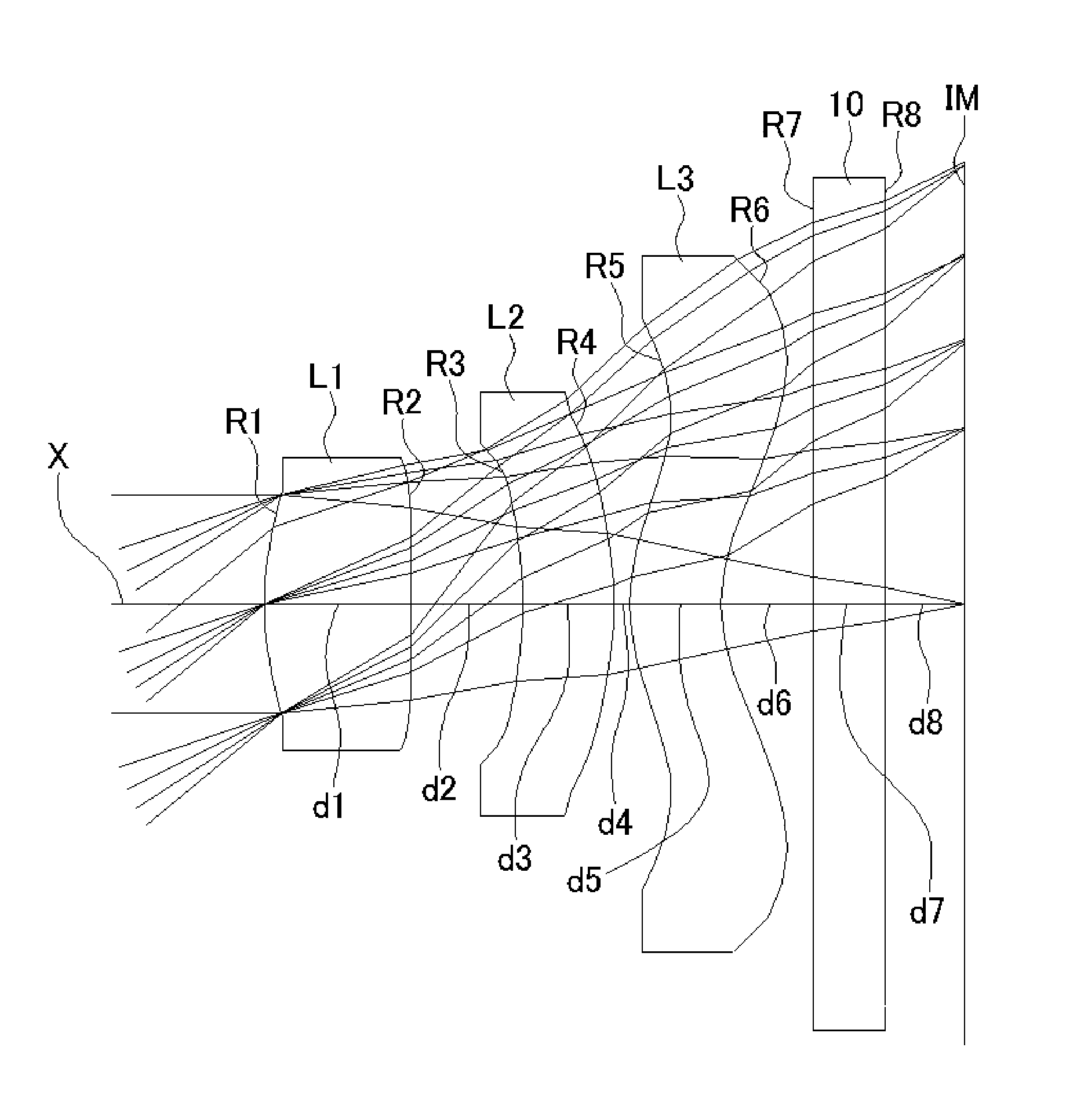
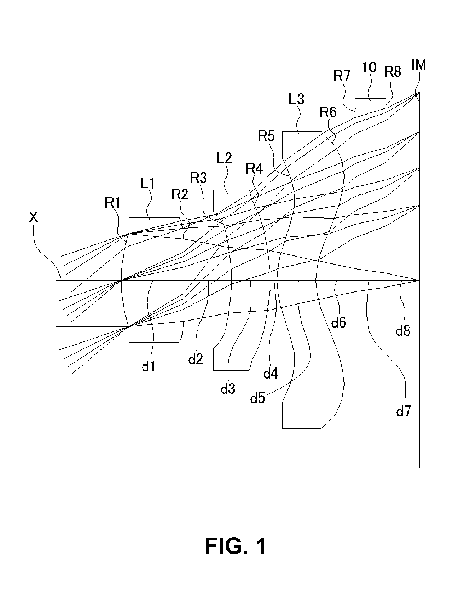
[0051]FIGS. 1, 4, 7, 10, and 13 are the schematic sectional views of the image lenses of which its data are respectively shown in Numerical Data Examples 1 to 5 in relation to the present embodiment.

[0052]Since each basic lens configuration in the embodiments described in Numerical Data Examples 1 to 5 is the same, the lens configuration of the embodiments will be explained by taking a reference with the lens schematic sectional view of Numerical Data Example 1.

[0053]Like as shown in FIG. 1, the imaging lens of the embodiment has a first lens L1 having positive refractive power; a second lens L2 having positive refractive power; and a third lens L3 having positive refractive power, which are arranged in this order from an object side to an image side of the imaging lens. The lens L1 to the lens L3 are made of a material with Abbe's number larger than of 50....


PUM


Abstract

An imaging lens includes a first lens; a second lens; and a third lens arranged from an object side to an image plane side. The first lens has an object-side surface having a positive curvature radius R1f and an image plane-side surface having a negative curvature radius R1r. The second lens has an object-side surface and an image plane-side surface with negative curvature radii. The third lens has an object-side surface and an image plane-side surface with positive curvature radii and formed as aspheric surfaces having inflexion points. When the whole lens system has a focal length f, the first lens has a focal length f1, the second lens has a focal length f2, and the third lens has a focal length f3, the imaging lens satisfies the following conditional expressions:f1<f2<f31.0<f1 / f<1.5−0.02<R1f / R1r<0

Description

BACKGROUND OF THE INVENTION AND RELATED ART STATEMENT[0001]The present invention relates to an imaging lens for forming an image on an imaging element such as a CCD sensor and a CMOS sensor and an imaging device equipped with the imaging lens. In particular, the present invention relates to an imaging lens suitable for mounting in a relatively small camera such as a cellular phone, a digital still camera, a portable information terminal, a security camera, an onboard camera, and a network camera. Further, the present invention relates to an imaging device equipped with the imaging lens.[0002]In these years, in place of cellular phones, which are mainly used for making phone calls, so-called smart phones, i.e., cellular phones with functions as portable information terminals (PDA) or personal computers, have been more widely used. In general, due to the smart phones are highly-functional as compared to the cellular phones, it is possible to use images taken by a camera thereof in var...

Claims


Application Information

Patent Timeline
Patent Type & Authority Patents(United States)
IPC IPC(8): G02B3/02G02B9/12G02B13/02
CPCG02B13/0035
Inventor KUBOTA, YOJIKUBOTA, KENICHIHIRANO, HITOSHIKURIHARA, ICHIRONODA, SAYURI
Owner TOKYO VISIONARY OPTICS CO LTD
Why Eureka
Try Eureka