Zoom lens and imaging apparatus

a zoom lens and imaging apparatus technology, applied in the field of zoom lenses and imaging apparatuses, can solve the problems of insufficient variable magnification ratio, insufficient field of view at the wide angle end, etc., and achieves short total length, high variable magnification ratio, and difficult to favorably correct various aberrations.

Active Publication Date: 2014-04-17
FUJIFILM CORP
View PDF0 Cites 1 Cited by
  • Summary
  • Abstract
  • Description
  • Claims
  • Application Information

AI Technical Summary

Benefits of technology

[0032]The above advantageous effects will become more prominent in the case that Conditional Formulae (1)′ and (2)′ are satisfied within the ranges defined in Conditional Formulae (1) and (2).
[0033]In the zoom lens of the present invention, the following advantageous effects can be obtained particularly in the case that Conditional Formula (3) is satisfied. That is, Conditional Formula (3) determines the power distribution of the third lens group with respect to the entire system. If the value of fw / f3 is less than or equal to the lower limit defined in Conditional Formula (3), the refractive power of the third lens group will become excessively small, and it will become difficult to obtain a high variable magnification ratio while maintaining a short total length. Inversely, if the value of fw / f3 is greater than or equal to the upper value defined in Conditional Formula (3), the refractive power of the third lens group will become excessively great, and it will become difficult to favorably correct various aberrations. The above shortcomings can be prevented in the case that Conditional Formula (3) is satisfied.
[0034]The above advantageous effects will become more prominent in the case that Conditional Formula (3)′ is satisfied within the range defined in Conditional Formula (3).
[0035]In the zoom lens of the present invention, the following advantageous effects can be obtained in the case that Conditional Formulae (2) and (4) are satisfied. That is, if Conditional Formula (2) is satisfied, the aforementioned advantageous effects can be obtained. Meanwhile, Conditional Formula (4) determines the power distribution of the first lens group with respect to the entire system. If the value of fw / f1 is less than or equal to the lower limit defined in Conditional Formula (4), the refractive power of the first lens group becomes excessively small, and it will become difficult to obtain a high variable magnification ratio while maintaining a short total length. Inversely, if the value of fw / f1 is greater than or equal to the upper limit defined in Conditional Formula (4), the refractive power of the first lens group will become excessively great, and it will become difficult to favorably correct various aberrations. The above shortcomings can be prevented in the case that Conditional Formula (4) is satisfied.
[0036]In addition, the following advantageous effects can be obtained in the case that the zoom lens of the present invention satisfies both Conditional Formulae (3)″ and (4). That is, the advantageous effects obtained by satisfying Conditional Formula (3)″ are basically the same as those obtained by satisfying Conditional Formulae (3) and (3)′ that similarly determine the range of the value of fw / f3. However, the advantageous effects become more prominent. Meanwhile, the same advantageous effects as those described above are obtained in the case that Conditional Formula (4) is satisfied.
[0037]In addition, in the case that the lens 42 and the lens 43 are cemented together to constitute a cemented lens in the zoom lens of the present invention, peripheral rays causing total reflection can be prevented, while the refractive power of each lens can be increased, which is desirable.

Problems solved by technology

In addition, the field of view at the wide angle end is insufficient, particularly in the zoom lens disclosed in Japanese Unexamined Patent Publication No. 4 (1992)-296809.
Further, the variable magnification ratio is insufficient in the zoom lens disclosed in U.S. Patent Application Publication No. 20010046383.
Still further, the field of view at the wide angle end and the variable magnification ratio are both insufficient in the zoom lens disclosed in U.S. Patent Application Publication No. 20070242367.

Method used


Image

  • Zoom lens and imaging apparatus
  • Zoom lens and imaging apparatus
  • Zoom lens and imaging apparatus

Examples


Embodiment Construction

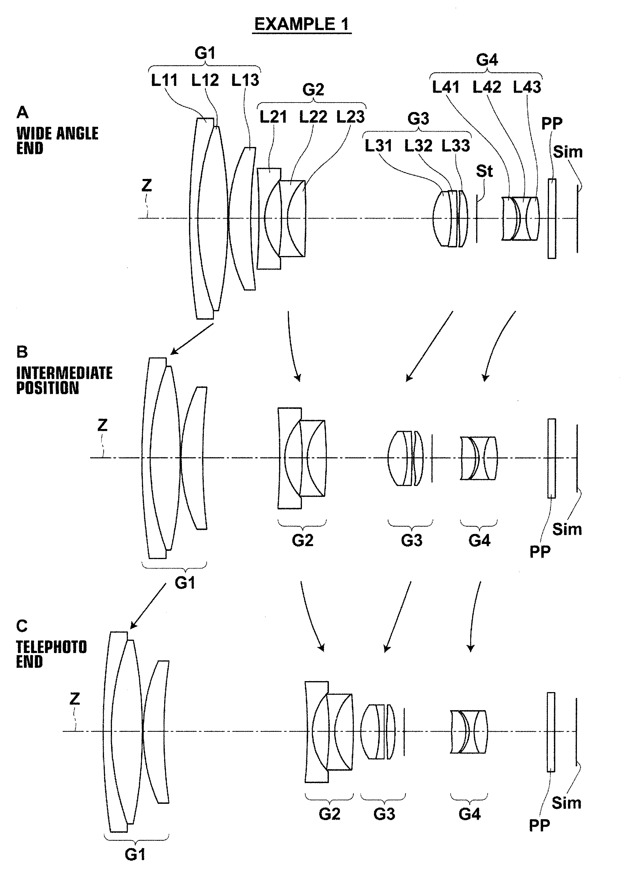
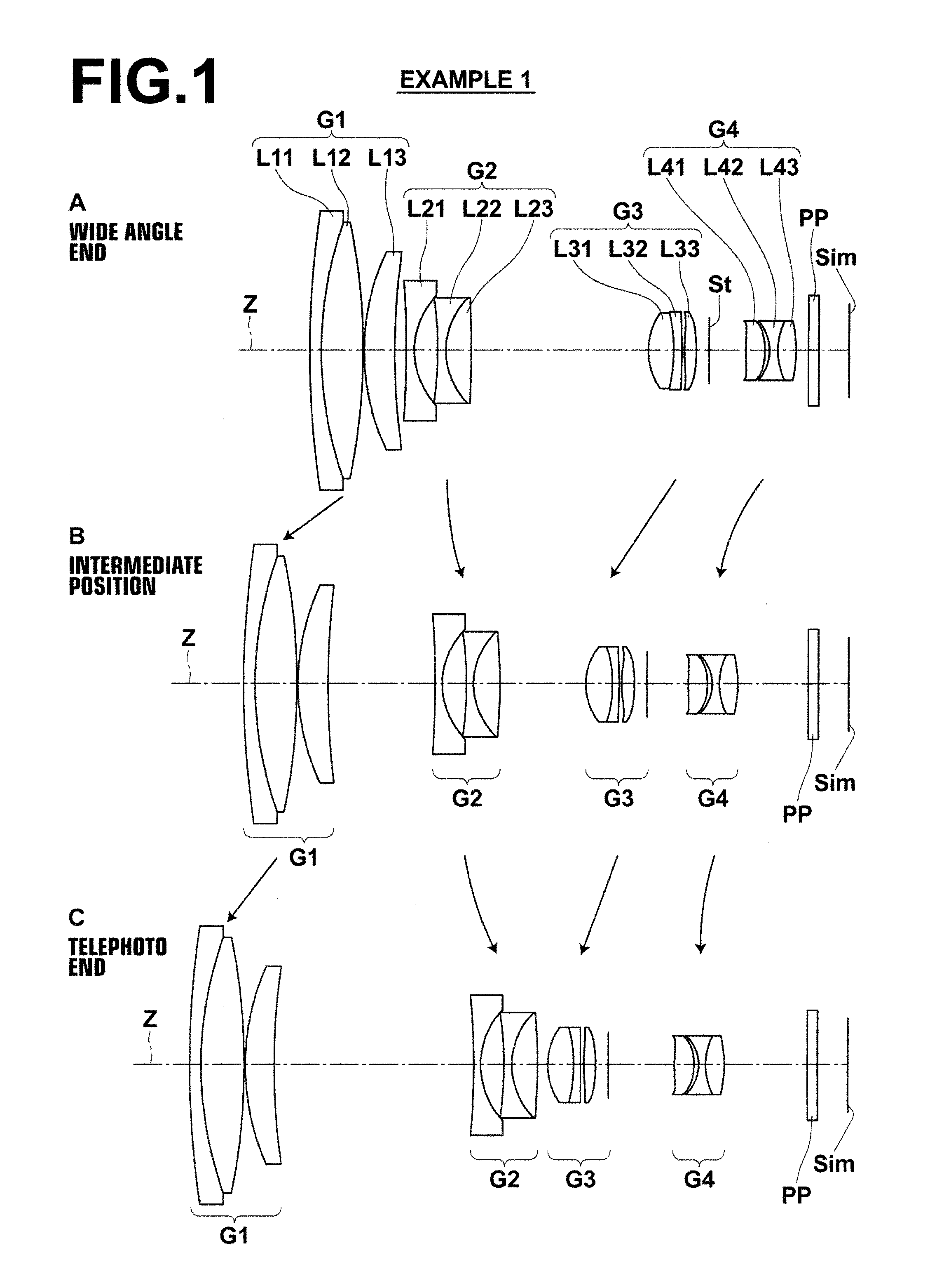
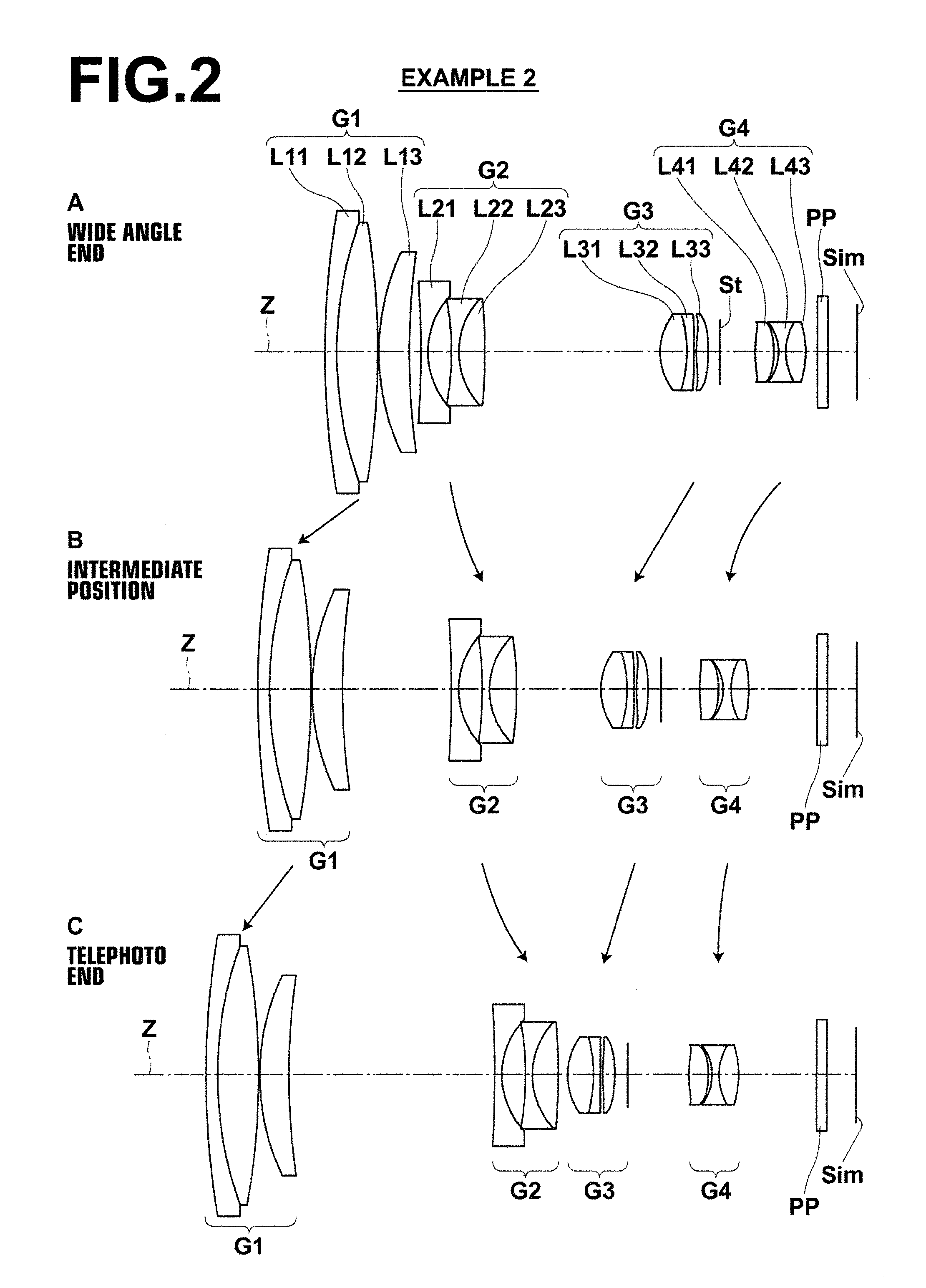
[0053]Hereinafter, embodiments of the present invention will be described in detail with reference to the attached drawings. FIG. 1 is a cross sectional diagram that illustrates the configuration of a zoom lens according to an embodiment of the present invention, and corresponds to a zoom lens of Example 1 to be described later. FIG. 2 through FIG. 6 are cross sectional diagrams that illustrate configurations of zoom lenses according to other embodiments of the present invention, and corresponds to zoom lenses of Examples 2 through 6 to be described later. The basic configurations of the embodiments illustrated in FIG. 1 through FIG. 11 are the same except that a third lens group G3 is constituted by two lenses in the embodiment of FIG. 3. The manners in which the configurations are illustrated are also the same. Therefore, the zoom lenses according to the embodiments of the present invention will be described mainly with reference to FIG. 1. Note that the third lens group G3 of the...


PUM


Abstract

A zoom lens includes: a first lens group having a positive refractive power; a second lens group having a negative refractive power; a third lens group having a positive refractive power; and a fourth lens group having a negative refractive power provided in this order from an object side. All of the lens groups move along an optical axis such that the distance between the first lens group and the second group gradually becomes greater, the distance between the second lens group and the third lens group gradually becomes smaller, and the distance between the third lens group and the fourth lens group gradually becomes greater when changing magnification from a wide angle end to a telephoto end. The fourth lens group practically includes a lens having a positive refractive power, a lens having a negative refractive power, and a lens having a positive refractive power.

Description

CROSS REFERENCE TO RELATED APPLICATIONS[0001]This application is a continuation of PCT / JP2012 / 003982 filed on Jun. 19, 2012, which claims foreign priority to Japanese Application No. 2011-138433 filed on Jun. 22, 2011. The entire contents of each of the above applications are hereby incorporated by reference.TECHNICAL FIELD[0002]The present invention is related to a zoom lens and an imaging apparatus. Particularly, the present invention is related to a zoom lens a zoom lens having a comparatively short total length, a high angle of view, and a high variable magnification ratio, and to an imaging apparatus equipped with such a zoom lens.BACKGROUND ART[0003]Conventionally, zoom lenses having a first lens group having a positive refractive power, a second lens group having a negative refractive power, a third lens group having a positive refractive power, and a fourth lens group having a negative refractive power, in this order from the object side, are known as disclosed in Japanese U...

Claims


Application Information

Patent Timeline
Patent Type & Authority Applications(United States)
IPC IPC(8): G02B15/14
CPCG02B15/14G02B15/173G02B15/144105
Inventor CHO, MICHIO
Owner FUJIFILM CORP
Why Eureka
Try Eureka