Snap-on module for selectively installing receiving element(s) to a mobile device

a mobile device and receiving element technology, applied in the field of spy module, can solve the problems of operator renegotiating orientation, less than ideal positioning of externally assembled spy reader,

Active Publication Date: 2015-03-31
INTERMEC IP CORP
View PDF25 Cites 647 Cited by
  • Summary
  • Abstract
  • Description
  • Claims
  • Application Information

AI Technical Summary

Problems solved by technology

The externally assembled RFID reader typically includes a large and bulky plastic case to contain the necessary equipment for the purposes of tag-reading.
Further, the location of the externally assembled RFID reader is less than ideal, as the equipment (e.g., antenna or sensor) within the plastic case is positioned at the rearward end of the handheld computer.
This inconvenient positioning causes an operator to renegotiate the orientation of the handheld computer each time the directional antenna communication or tag-reading functionality is to be employed.

Method used


Image

  • Snap-on module for selectively installing receiving element(s) to a mobile device
  • Snap-on module for selectively installing receiving element(s) to a mobile device
  • Snap-on module for selectively installing receiving element(s) to a mobile device

Examples


Embodiment Construction

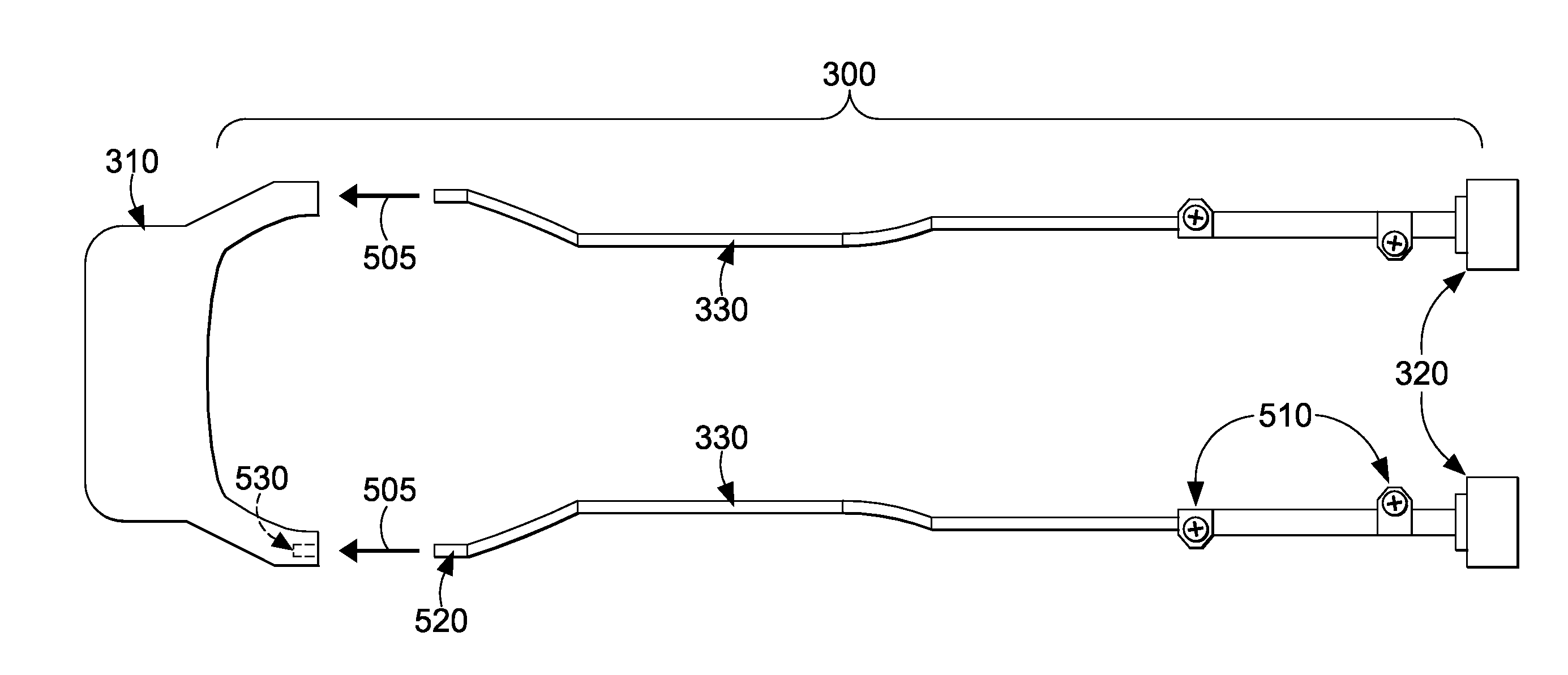
[0019]Embodiments provide methods and an apparatus for selectively attaching a snap-on module, which is connected to sensor(s) or antenna(s) located at a forward end of a mobile device, to a rearward end of the mobile device. The rearward end, or “communications end,” of the handheld device is configured to physically engage with the snap-on module and to electronically interface with equipment and / or media coupled to the snap-on module. Thus, embodiments of the present invention solve the problematic design issues facing conventional RFID readers, as discussed above. Further, the positioning of the snap-on module and the sensor(s) or antenna(s) at opposite ends of the mobile device, respectively, gain the following advantages: retrofitting to a wide range of handheld computers (e.g., RFID readers); providing aftermarket adaptability to legacy mobile devices; enabling direct communication for mobile devices, thereby limiting the requirement of including Wi-Fi and BT radios; supporti...


PUM

PropertyMeasurementUnit
poweraaaaaaaaaa
transmissionsaaaaaaaaaa
resilientaaaaaaaaaa

Abstract

An apparatus and method for selectively attaching sensor(s) or antenna(s) to a mobile device at a convenient location are provided. The mobile device includes a body and a processing unit housed within the body for running an application, where the body includes a forward end and a rearward end that supports engagement with a charging dock. In addition, the rearward end accepts engagement of a snap-on module that physically assembles to and electronically interfaces with the mobile device. The antennas or sensors are externally mounted to the mobile device at a location proximate to the forward end of the body. Further, these antennas or sensors are interconnected to the snap-on module using media-routing conduit(s) that are configured to carry signals from the antennas or sensors to the snap-on module for distribution as an input to the application running on the processing unit.

Description

CROSS-REFERENCE TO RELATED APPLICATIONS[0001]This application claims the benefit of U.S. Provisional Application No. 61 / 570,617, filed Dec. 14, 2011, now pending, entitled “SNAP-ON MODULE FOR SELECTIVELY INSTALLING RECEIVING ELEMENT(S) TO A MOBILE DEVICE,” which is herein incorporated by reference.STATEMENT REGARDING FEDERALLY SPONSORED RESEARCH OR DEVELOPMENT[0002]Not applicable.BACKGROUND OF THE INVENTION[0003]This invention relates to a snap-on module that allows for adding a sensor (e.g., radio frequency identification (RFID) reader) or an antenna (e.g., directional antenna) to a mobile device, such as a handheld computer. More particularly, embodiments of the present invention pertain to a method and apparatus for combining the snap-on module to a rearward end of the mobile device while conveniently locating the sensor or antenna at a forward end of the mobile device.[0004]Currently, there are two prevalent approaches for incorporating tag-reading technology within a handheld c...

Claims


Application Information

Patent Timeline
Patent Type & Authority Patents(United States)
IPC IPC(8): G06K7/00G06K7/10G06K7/14G06F1/16H01P11/00
CPCG06F1/1684G06K7/0004G06K7/10316H01P11/00G06K7/10386Y10T29/49018
Inventor HOPPER, SCOTT RLAM, SANDER
Owner INTERMEC IP CORP
Why Eureka
Try Eureka