
Piezoelectric/electrostrictive element

a piezoelectric/electrostrictive element and electromechanical technology, applied in the field of piezoelectric/electrostrictive elements, can solve the problems of increasing the cost of production, so as to achieve less of a decline in the insulation resistance value

Active Publication Date: 2015-03-31
NGK INSULATORS LTD
View PDF7 Cites 0 Cited by
  • Summary
  • Abstract
  • Description
  • Claims
  • Application Information

AI Technical Summary

Benefits of technology

The present invention provides a piezoelectric / electrostrictive element that can maintain a desired displacement and insulation resistance value even when used under a high-humidity environment. This is achieved by using a specific ceramic composition where a small part of the lead ion is substituted with a strontium ion and a part of a composition is substituted with a composition containing aluminum. The resulting element has improved performance compared to conventional elements.

Problems solved by technology

However, in the case of using the piezoelectric / electrostrictive actuator repetitively, the insulation resistance value of the piezoelectric / electrostrictive actuator may decline over time.
In particular, in the case of using the piezoelectric / electrostrictive actuator under a high-humidity environment, the insulation resistance value may decline to a great extent.
Such a decline in the insulation resistance value under a high-humidity environment is a problem to be solved from the viewpoint of high reliability in recent years.

Method used


Image

  • Piezoelectric/electrostrictive element
  • Piezoelectric/electrostrictive element
  • Piezoelectric/electrostrictive element

Examples


example 1

[0075]Each of the raw materials of PbO, TiO2, ZrO2, NiO, Nb2O5, Al2O3, NiO, and SrCO3 was weighed so as to have a composition formula of (Pb0.980Sr0.020)1,000{(Ti0.512Zr0.488)0.850 (Ni1 / 3Nb2 / 3)0.070(Al1 / 2Nb1 / 2)0.080}O3. These are mixed in a ball mill for 24 hours together with a predetermined amount of water to obtain prepared slurry. The obtained prepared slurry was put in a hot air drier to evaporate water and dried to obtain a raw material powder.

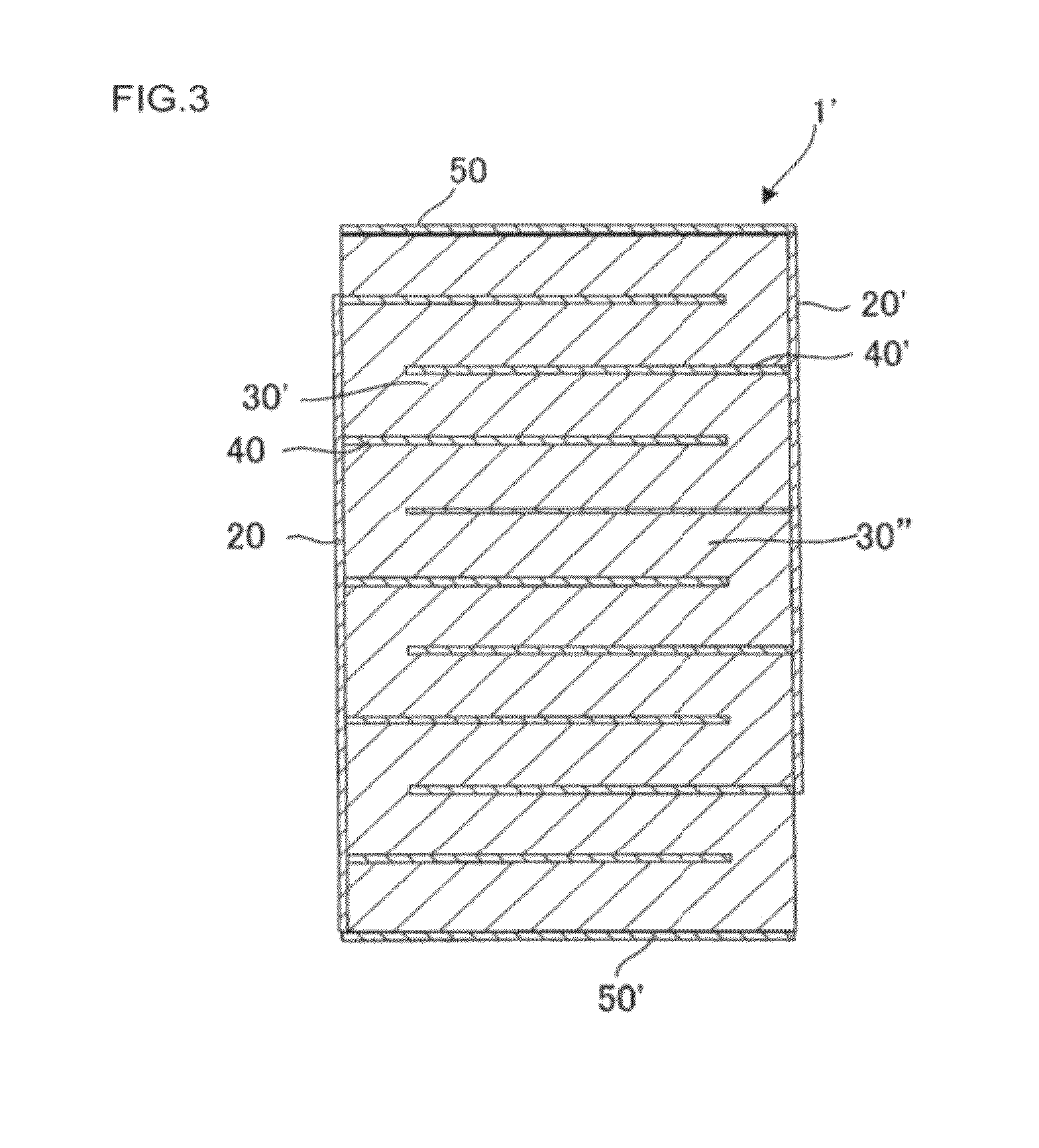
[0076]After the mixed powder obtained above was calcined, it was pulverized to prepare a powder of a piezoelectric / electrostrictive ceramic composition. With the powder, a piezoelectric / electrostrictive tape having a thickness of 12 μm was formed by a doctor blade method. A Pt electrode was formed on one face of the piezoelectric / electrostrictive tape in such a manner that the electrode might have a thickness of 1 μm after firing. After three layers of this structure were laminated to obtain a laminated body, a layer of the piezoelectric...

examples 2 to 10

, Comparative Examples 1 to 7

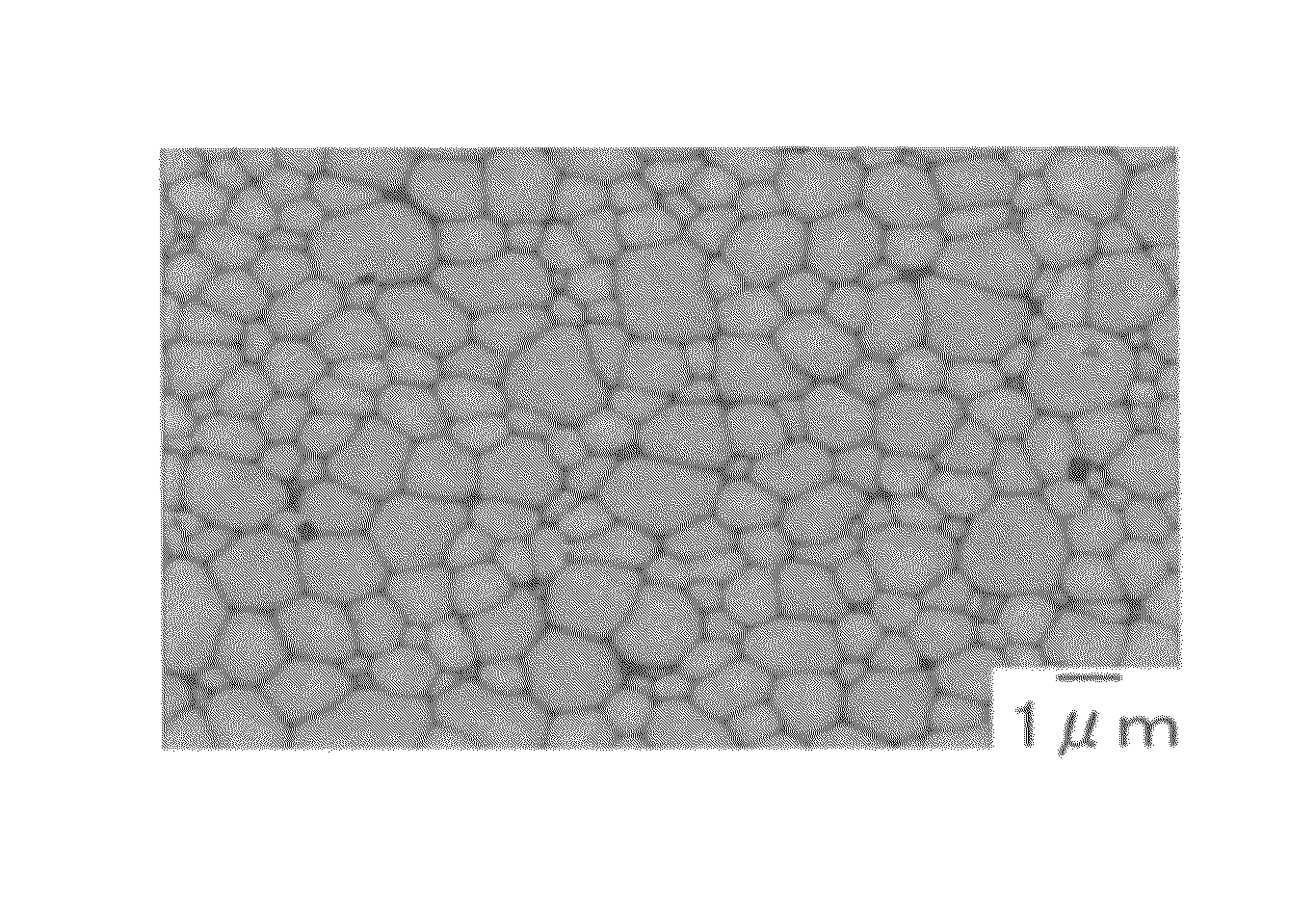
[0077]Each of the laminate type piezoelectric / electrostrictive actuators (piezoelectric / electrostrictive elements) was manufactured in the same manner as in Example 1 except that the used amounts of the raw materials were changed to obtain the parameters in the composition formula as shown in Table 1. Incidentally, an electron micrograph of the piezoelectric / electrostrictive body constituting the piezoelectric / electrostrictive element of Comparative Example 5 is shown in FIG. 5A.

[0078]In Table 1, each of the parameters corresponds to a parameter in the following composition formula:

(Pb1-xSrx)α{(Ti1-yZry)a(Niβ / 3Nb2 / 3)b(Alγ / 2Nb1 / 2)c}O3.

[0079]

TABLE 1Parameter in composition formula ofpiezoelectric / electrostrictive ceramic compositionxyabcαβγUpper limit0.0300.5400.9100.3600.0801.0301.0301.030Lower limit0.0050.4500.5800.0700.0200.9700.9700.970Example 10.0200.4880.8500.0700.0801.0001.0001.000Example 20.0100.4880.8600.1000.0401.0001.0001.000Example 30.0050.4880...

example 11

[0083]A laminate type piezoelectric / electrostrictive actuator (piezoelectric / electrostrictive element) was manufactured in the same manner as in Example 1 except that the firing temperature was 1100° C. Incidentally, an electron micrograph of the piezoelectric / electrostrictive body constituting the piezoelectric / electrostrictive element of Example 11 is shown in FIG. 4B.


PUM

PropertyMeasurementUnit
average grain diameteraaaaaaaaaa
thicknessaaaaaaaaaa
thicknessaaaaaaaaaa

Abstract

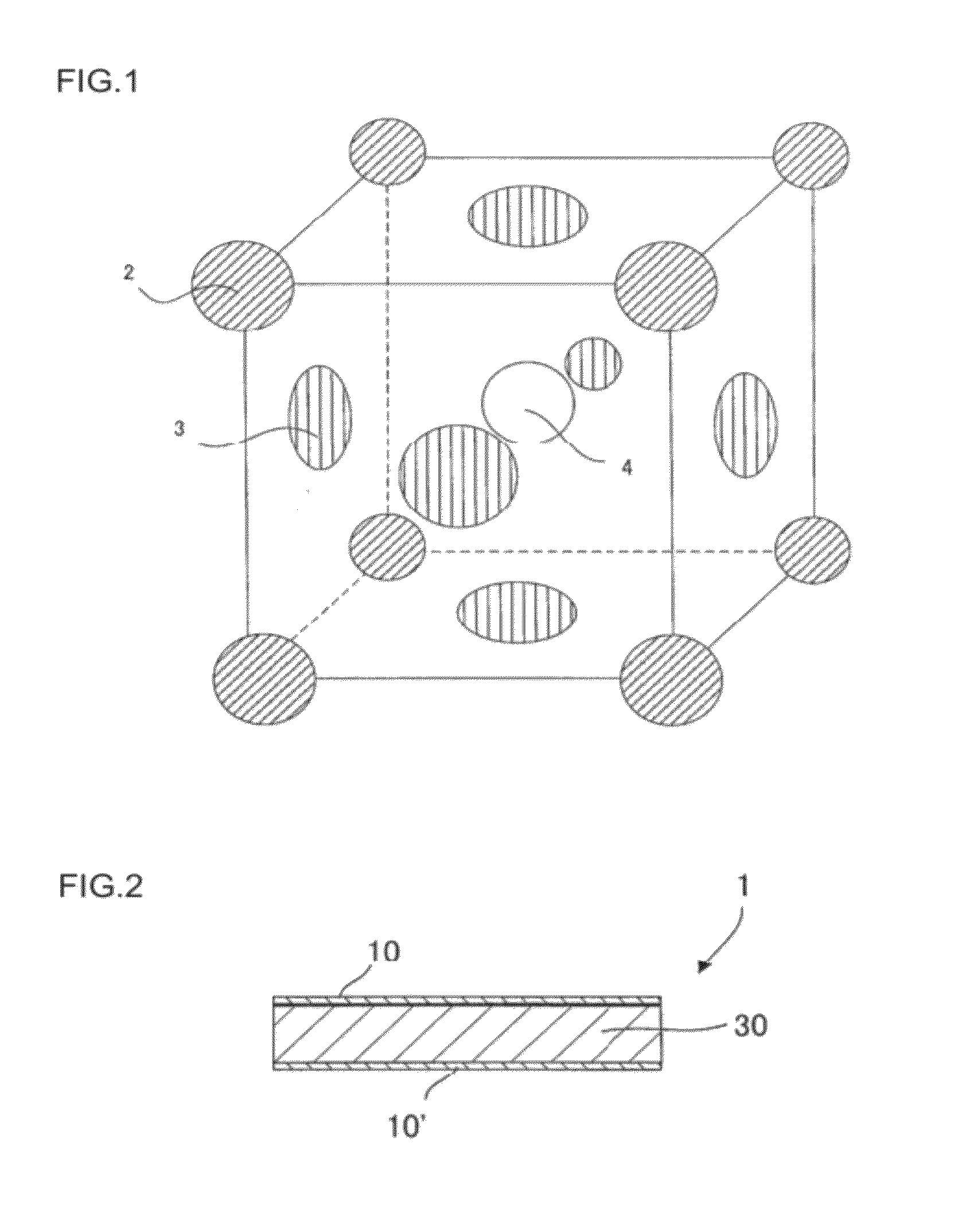
There is provided a piezoelectric / electrostrictive element 1 comprising a piezoelectric / electrostrictive body 30 made of a piezoelectric / electrostrictive ceramic composition containing Pb(Ni1 / 3Nb2 / 3)O3—PbTiO3—PbZrO3 ternary solid solution system composition as the main components, and an electrode disposed on the piezoelectric / electrostrictive body, wherein the ternary solid solution system composition is represented by the following composition formula:(Pb1-xSrx)α{(Ti1-yZry)a(Niβ / 3Nb2 / 3)b(Alγ / 2Nb1 / 2)c}O3 (where 0.005≦x≦0.03, 0.45≦y≦0.54, 0.58≦a≦0.91, 0.07≦b≦0.36, 0.02≦c≦0.08, 0.97≦α≦1.03, 0.97≦β≦1.03, 0.97≦γ≦1.03, and (a+b+c=1.000)).

Description

FIELD OF THE INVENTION[0001]The present invention relates to a piezoelectric / electrostrictive element. More specifically, the present invention relates to a piezoelectric / electrostrictive element using a piezoelectric / electrostrictive body made of a PNN-PZT type piezoelectric / electrostrictive ceramic composition.BACKGROUND OF THE INVENTION[0002]In recent years, there has been used a small piezoelectric / electrostrictive element for a power source of a HD (hard disk) head, a motor of a cell phone or a digital camera, a power source for ejecting ink of an ink-jet printer, or the like.[0003]In a film type piezoelectric / electrostrictive actuator, it is effective to make the thickness of the film thin in order to obtain a large displacement in the case of using the actuator in the Same driving electric field, and the thickness can be reduced to about 10 μm or less. A piezoelectric / electrostrictive ceramic composition used for such a film type piezoelectric / electrostrictive actuator is req...

Claims


Application Information

Patent Timeline
Patent Type & Authority Patents(United States)
IPC IPC(8): H01L41/18C04B35/00B32B18/00C04B35/493H01L41/083H01L41/187H01L41/22H01L41/39
CPCH01L41/1876B32B18/00C04B35/493H01L41/083C04B2235/3212C04B2235/3217C04B2235/3251C04B2235/3279C04B2235/5436C04B2235/5445C04B2235/6025C04B2235/768C04B2235/785C04B2235/786C04B2237/348C04B2235/3213H10N30/50H10N30/8554
Inventor HIBINO, TOMOHIKO
Owner NGK INSULATORS LTD
Learn More