Test flow to detect a latent leaky bit of a non-volatile memory

a non-volatile memory and test flow technology, applied in the field of non-volatile memory, can solve problems such as customer return of an nvm uni

Active Publication Date: 2015-03-31
NXP USA INC
View PDF13 Cites 2 Cited by
  • Summary
  • Abstract
  • Description
  • Claims
  • Application Information

AI Technical Summary

Problems solved by technology

Consequently, latent leaky bits may cause NVM (e.g., flash memory) qualification failures and result in customer returns of an NVM unit.

Method used


Image

  • Test flow to detect a latent leaky bit of a non-volatile memory
  • Test flow to detect a latent leaky bit of a non-volatile memory
  • Test flow to detect a latent leaky bit of a non-volatile memory

Examples


Embodiment Construction

[0013]In the following detailed description of exemplary embodiments of the invention, specific exemplary embodiments in which the invention may be practiced are described in sufficient detail to enable those skilled in the art to practice the invention, and it is to be understood that other embodiments may be utilized and that logical, architectural, programmatic, mechanical, electrical and other changes may be made without departing from the spirit or scope of the present invention. The following detailed description is, therefore, not to be taken in a limiting sense, and the scope of the present invention is defined only by the appended claims and their equivalents.

[0014]In one conventional NVM test flow, a burn-in (BI) program / erase (P / E) cycling test is employed to screen out bad NVM units whose cycling performance deteriorates to a certain level (e.g., when an erase pulse count exceeds a screen limit). It is common for units with latent leaky bits to show leaky behavior only a...


PUM


Abstract

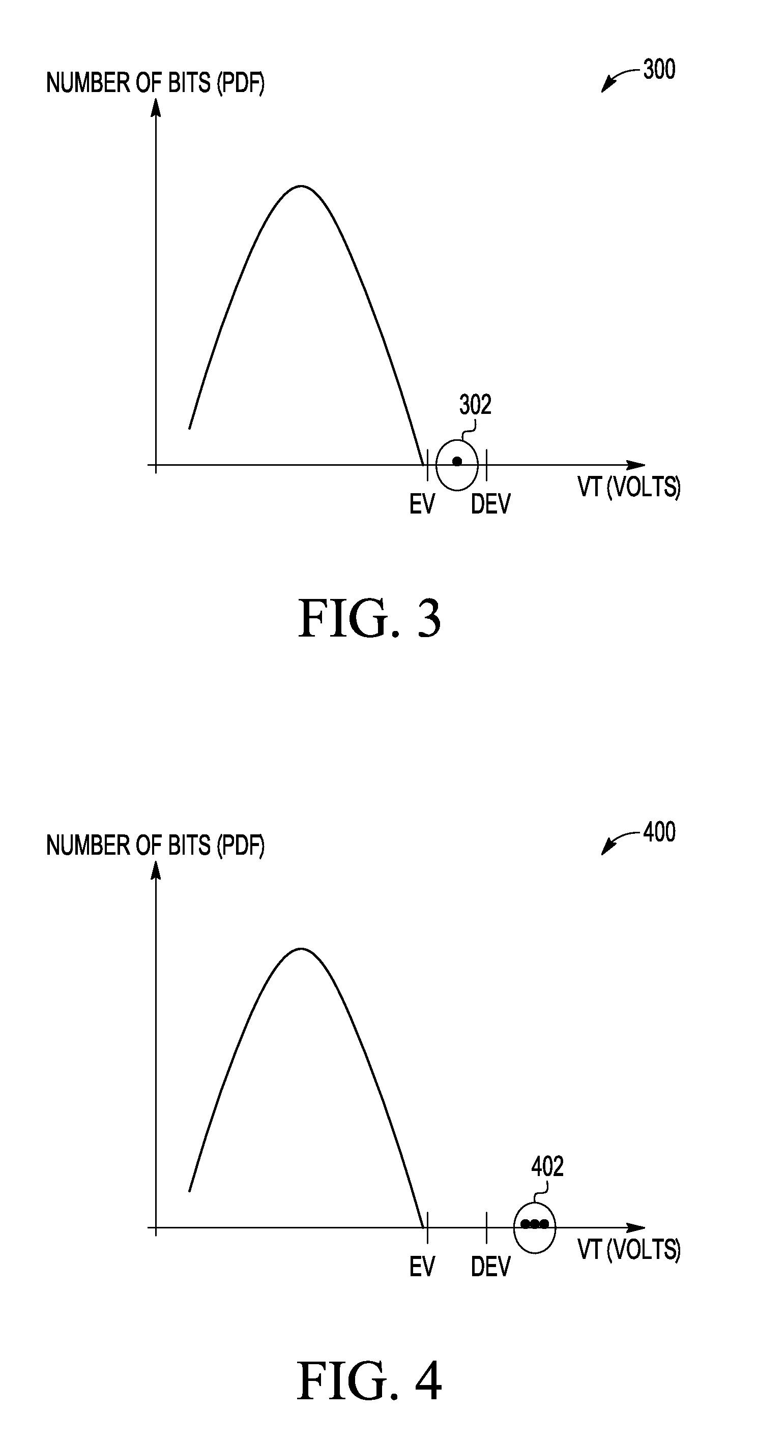
A technique for detecting a leaky bit of a non-volatile memory includes erasing cells of a non-volatile memory. A bias stress is applied to the cells subsequent to the erasing. An erase verify operation is performed on the cells subsequent to the applying a bias stress to the cells. Finally, it is determined whether the cells pass or fail the erase verify operation based on whether respective threshold voltages of the cells are below an erase verify level.

Description

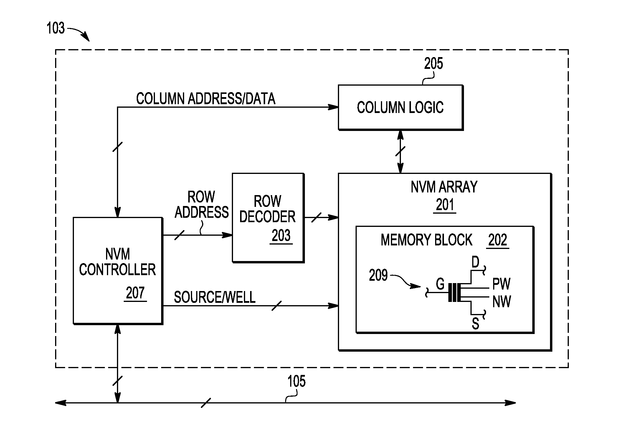
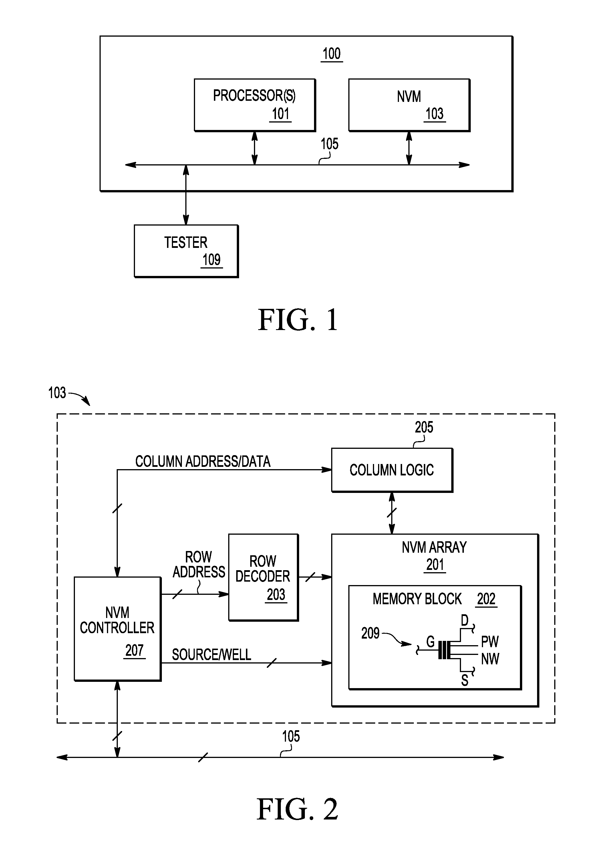
BACKGROUND[0001]1. Field[0002]This disclosure relates generally to non-volatile memory and, more specifically, to test flows to detect a latent leaky bit of a non-volatile memory.[0003]2. Related Art[0004]Non-volatile memory (NVM) is memory that retains stored information when unpowered. Examples of NVM include read-only memory (ROM), flash memory, ferro-electric random access memory (FRAM), and magneto-resistive random access memory (MRAM). NVM, similar to volatile memory, may have cells (bits) that exhibit leaky behavior. For example, an NVM cell that was programmed to a digital one may transition over time to a digital zero. As another example, an NVM cell that was programmed to a digital zero may transition over time to a digital one. Conventional NVM test flows have not generally screened out latent leaky cells (bits) that only transition after a number of cycles (e.g., several hundred cycles) or transition after a certain number of cycles and stop and then transition again aft...

Claims


Application Information

Patent Timeline
Patent Type & Authority Patents(United States)
IPC IPC(8): G11C11/34G11C29/50
CPCG11C29/50004G11C29/50016G11C2029/5006
Inventor MU, FUCHENBOGUCKI, PAUL AHE, CHEN
Owner NXP USA INC
Why Eureka
Try Eureka