
Radio communication device, signal strength output method and radio communication system

a radio communication system and signal strength technology, applied in the direction of transmission monitoring, modulation, synchronisation arrangement, etc., can solve the problems of short communication range, relatively narrow communication range, and short time for data transmission, and achieve the effect of less processing amoun

Active Publication Date: 2015-03-31
SONY CORP
View PDF8 Cites 15 Cited by
  • Summary
  • Abstract
  • Description
  • Claims
  • Application Information

AI Technical Summary

Benefits of technology

The present invention provides a radio communication device, signal strength output method, and radio communication system that can quickly and easily obtain the strength of received signals with minimal processing. This results in a more efficient and effective communication system.

Problems solved by technology

However, a short-range high-speed radio communication such as TransferJet (registered trademark) has a relatively narrow communication range, and takes a short time for data transmission.
Therefore, unless a change in the received signal strength is reflected promptly on RSSI signals, its value does not make sense.

Method used


Image

  • Radio communication device, signal strength output method and radio communication system
  • Radio communication device, signal strength output method and radio communication system
  • Radio communication device, signal strength output method and radio communication system

Examples


Embodiment Construction

)

[0027]Hereinafter, preferred embodiments of the present invention will be described in detail with reference to the appended drawings. Note that, in this specification and the appended drawings, structural elements that have substantially the same function and structure are denoted with the same reference numerals, and repeated explanation of these structural elements is omitted.

[0028]Preferred embodiments of the present invention will be described hereinafter in the following order:

[0029]1. Overview of a radio communication system

[0030]2. An exemplary configuration of a radio communication device

[0031]3. Timing chart

[0032]4. Conclusion

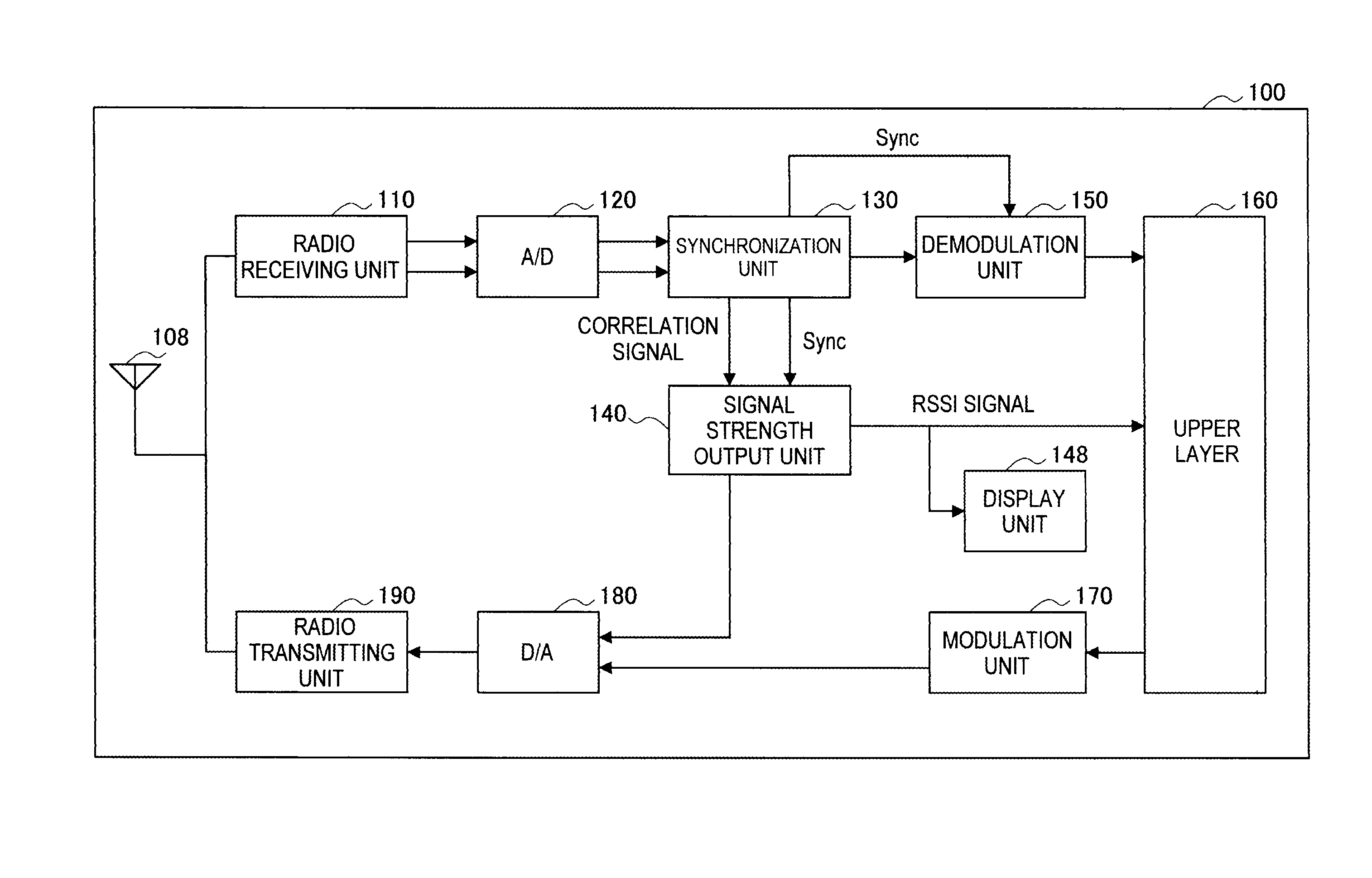
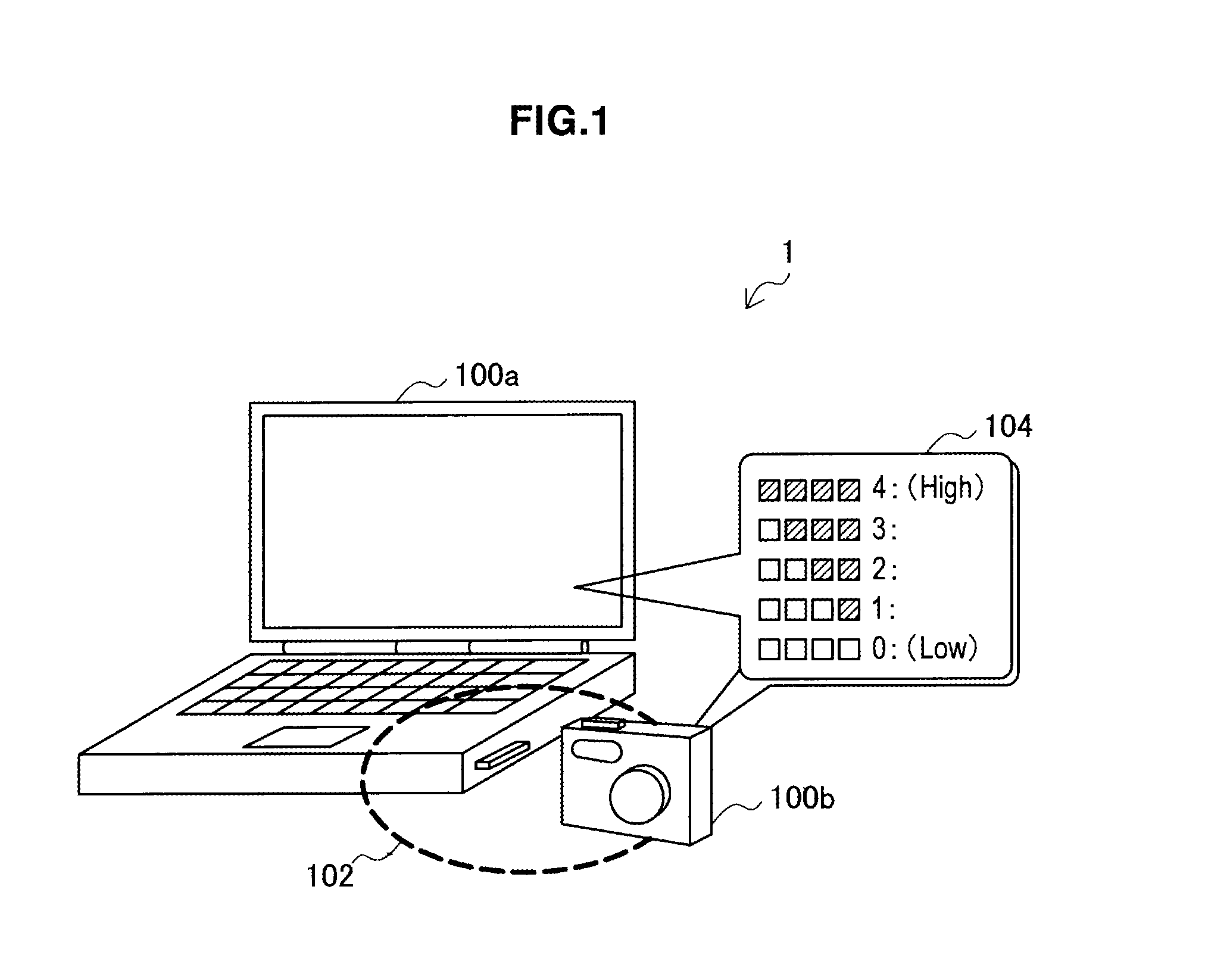
[0033]Firstly, the overview of a radio communication system according to an embodiment of the present invention is described with reference to FIG. 1. FIG. 1 is a schematic view showing the overview of a radio communication system according to an embodiment. Referring to FIG. 1, the radio communication system 1 includes radio communication devices 10...


PUM


Abstract

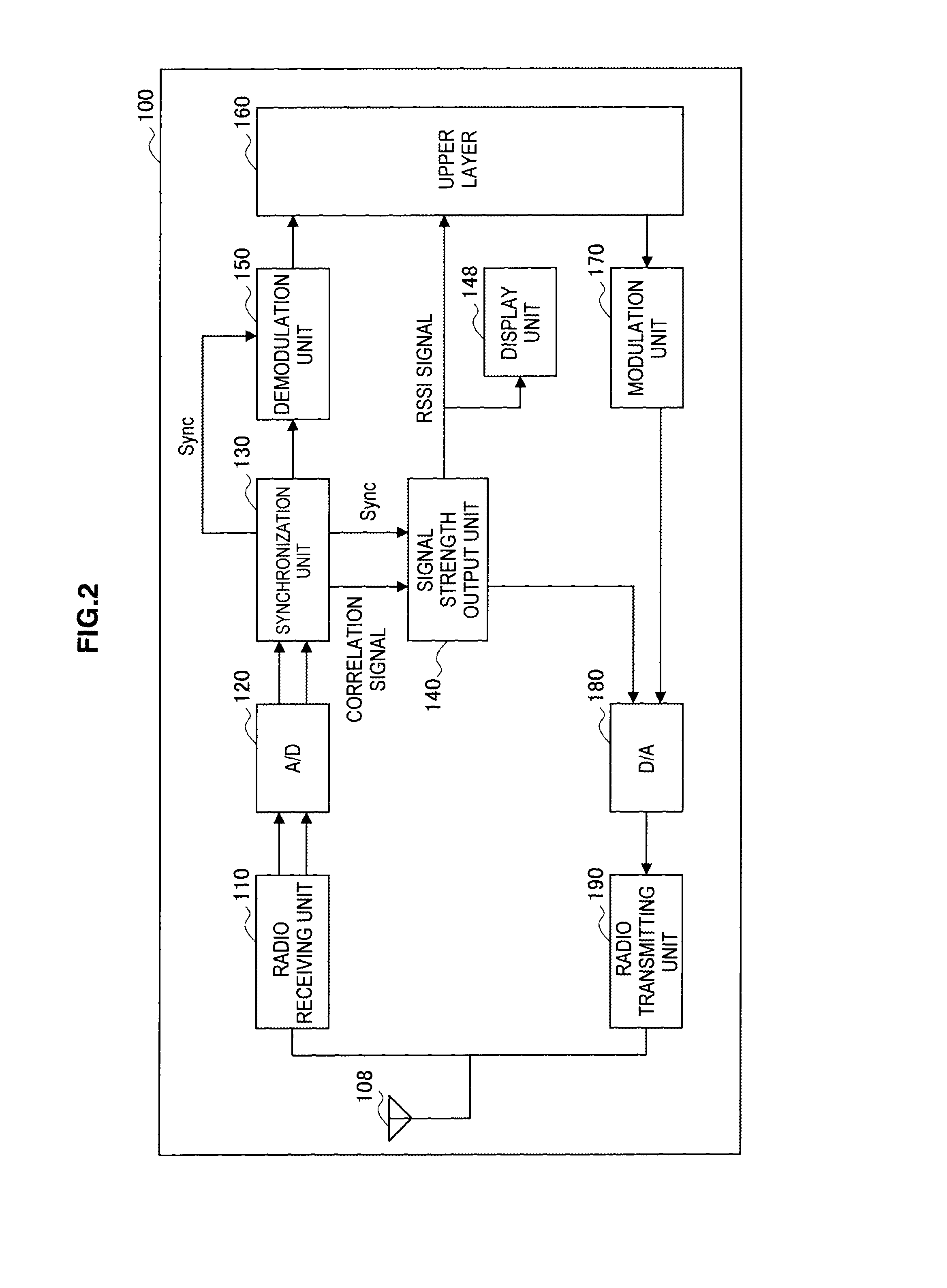
There is provided a radio communication device including a radio receiving unit to receive a radio signals, a synchronization unit to detect synchronization based on a result of a correlation for received signals output from the radio receiving unit, and a signal strength output unit to output, as signal strength of the received signals that is RSSI (Received Signal Strength Indicator) value, a level of a correlation signal that is output as a result of the correlation by the synchronization unit.

Description

CROSS REFERENCE TO RELATED APPLICATION[0001]This application claims priority to Japanese Priority Patent Application JP 2009-233025, filed in the Japan Patent Office on Oct. 7, 2009, the entire content of which is hereby incorporated by reference.BACKGROUND OF THE INVENTION[0002]1. Field of the Invention[0003]The present invention relates to a radio communication device, a signal strength output method and a radio communication system.[0004]2. Description of the Related Art[0005]Generally, a radio communication device includes a function called RSSI (Received Signal Strength Indicator) which measures signal strength of received radio signals. The signal strength measured by such RSSI function is notified to a user through a screen of a display device, or to be used as a parameter for controlling an output level of signals from a local device.[0006]Examples of a technological development regarding the RSSI function are Japanese Unexamined Patent Application Publication No. 2004-30462...

Claims


Application Information

Patent Timeline
Patent Type & Authority Patents(United States)
IPC IPC(8): H04B17/00H04B1/16H04B1/40H04B17/318H04W56/00H04W88/02
CPCH04W56/00H04B1/40
Inventor WATANABE, KATSUMI
Owner SONY CORP
Learn More