
Drying furnace and drying method

a drying furnace and dryer technology, applied in the direction of drying machines with progressive movements, furnaces, lighting and heating apparatus, etc., can solve the problems of energy saving and longer drying time, and achieve the effect of reducing unnecessary hea

Inactive Publication Date: 2015-04-07
HONDA MOTOR CO LTD
View PDF33 Cites 20 Cited by
  • Summary
  • Abstract
  • Description
  • Claims
  • Application Information

AI Technical Summary

Benefits of technology

[0012]Embodiments of the present invention provide a drying technique capable of reducing unnecessary amount of heat which was given to easy-heating regions of an object.

Problems solved by technology

Consequently, drying time becomes longer.
This is undesirable from the viewpoint of energy saving.

Method used


Image

  • Drying furnace and drying method
  • Drying furnace and drying method
  • Drying furnace and drying method

Examples


embodiment

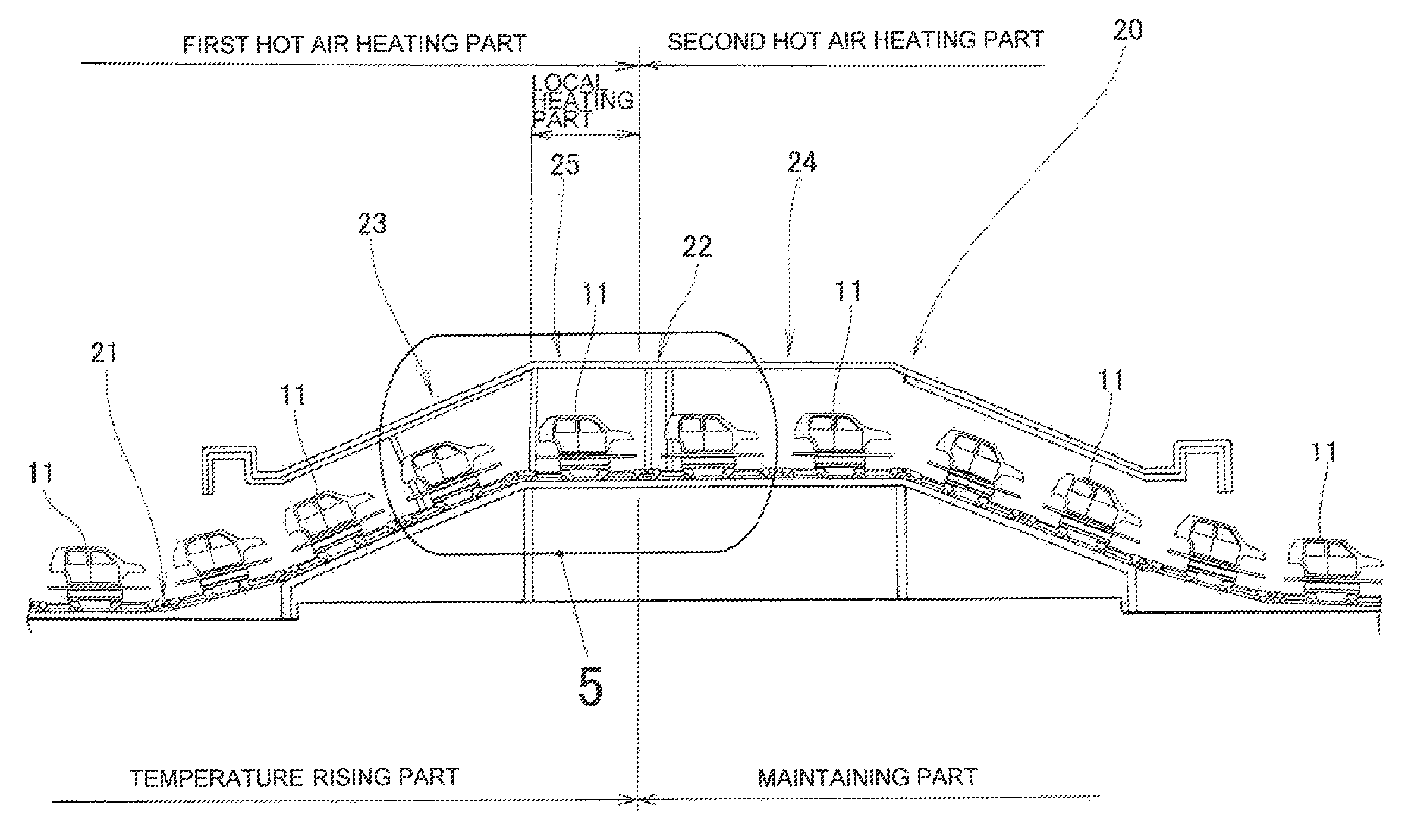
[0046]Hereinafter, embodiments of the present invention will be described with reference to the accompanying drawings. The drawings are viewed in directions of symbols. In the present embodiment, an object to be dried is a vehicle body. A side sill is represented as an example of the hard-heating region which has a larger heat capacity than the other regions and a door outer panel is represented as an example of the other region. Further, in the present embodiment, the vehicle body put into the drying furnace has been subjected to a painting operation by painting equipment which is provided at an upstream side of the drying furnace.

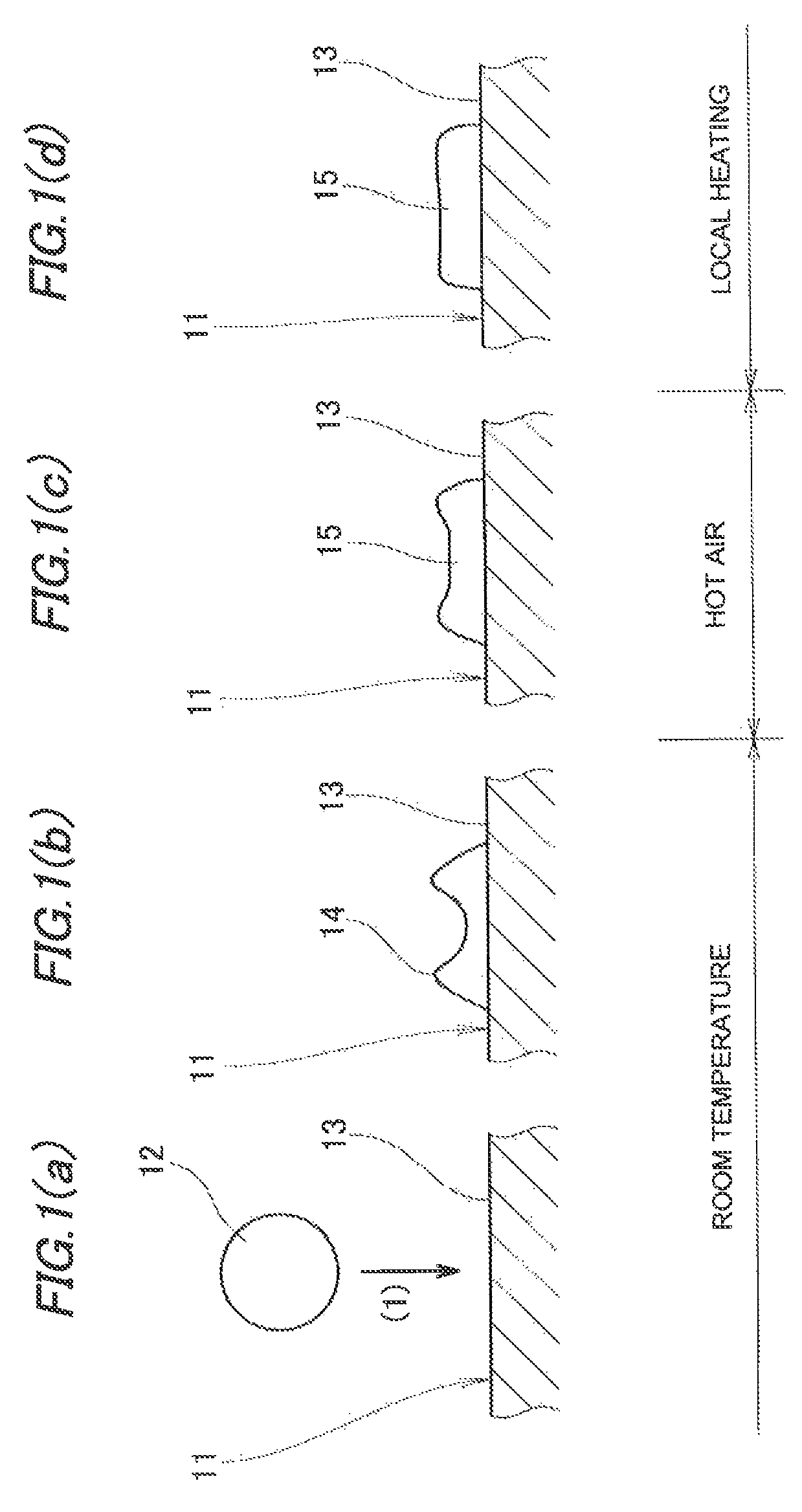
[0047]As shown in FIG. 1 (a), when atomized paint is sprayed on a vehicle body 11 (which will be described in detail below), paint particles 12 are directed to a surface 13 of the vehicle body 11 as indicated by arrow (1). At this time, a surface temperature of the vehicle body 11 is at room temperature.

[0048]As the paint particles 12 collide with the sur...


PUM


Abstract

A drying furnace (20) for drying an object (11) by hot air is provided with a heater (36, 38, 43, 45) that applies radiant heat to a hard-heating region (35, 42) having a larger heat capacity than the other region (37, 44) in the object (11) so as to heat the hard-heating region (35, 42) to a temperature approximate to a temperature of the other region (37, 44).

Description

CROSS-REFERENCED TO RELATED APPLICATION[0001]This application is a National Phase entry of International Application PCT / JP2011 / 061911, filed May 24, 2011, which claims priority to Japanese Patent Application No. 2010-120620, filed May 26, 2010, the disclosure of the prior applications are hereby incorporated in their entirety by reference.TECHNICAL FIELD[0002]The present invention relates to a drying technique for drying an object by hot air.BACKGROUND ART[0003]As an example of a drying furnace, there is a hot air circulation drying furnace. In this drying furnace, an object is dried by hot air which is circulating. The object is often a combination of a plurality of members and includes thick portions and thin portions. The thick portions have a large heat capacity and thus are regions (hereinafter, referred to as “hard-heating regions”) which are difficult to be warm. On the contrary, the thin portions have a small heat capacity and thus are regions (hereinafter, referred to as “...

Claims


Application Information

Patent Timeline
Patent Type & Authority Patents(United States)
IPC IPC(8): F26B3/28B05D3/02F26B3/30F26B15/16
CPCF26B15/16F26B3/30F26B3/283F26B2210/12B05D3/0263B05D3/0272
Inventor SATO, WATARU
Owner HONDA MOTOR CO LTD
Learn More