Adaptive signal processing

a signal processing and signal technology, applied in the field of signal processing, can solve the problems of high latency and pipeline delay of the process, and achieve the effect of minimizing the measure of the error

Inactive Publication Date: 2015-04-07
GRASS VALLEY LTD
View PDF10 Cites 0 Cited by
  • Summary
  • Abstract
  • Description
  • Claims
  • Application Information

AI Technical Summary

Benefits of technology

[0012]The invention consists in one aspect in a method and apparatus for adaptive signal processing in which the parameters of the process are adapted in order to minimize a measure of the error between a delayed version of its output and that of a reference process.
[0017]The invention consists in yet another aspect in a method of signal processing to transform an input signal to a processed signal, comprising the steps of conducting a reference process on an input signal; conducting in parallel an adaptive process on said input signal to form the processed signal, said process having controllable parameters; measuring an error between a delayed version of the adaptive process output and the reference process output; and adapting the adaptive process by controlling said parameters to reduce said error.
[0019]Preferably, the step of adapting the adaptive process serves to minimize said error over a time period not less than said delay.

Problems solved by technology

However, since a causal system cannot in reality access future samples, the process has to wait until the last required input sample has arrived before it can produce its output.
This waiting period is known as the latency or pipeline delay of the process.
For example, if the object is to smooth or low-pass filter the signal, then many input samples are required, and if constant group delay is required, the filter also needs to be symmetric, so about half the samples need to be “future” samples, giving rise to a high latency.

Method used


Image

  • Adaptive signal processing
  • Adaptive signal processing
  • Adaptive signal processing

Examples


Embodiment Construction

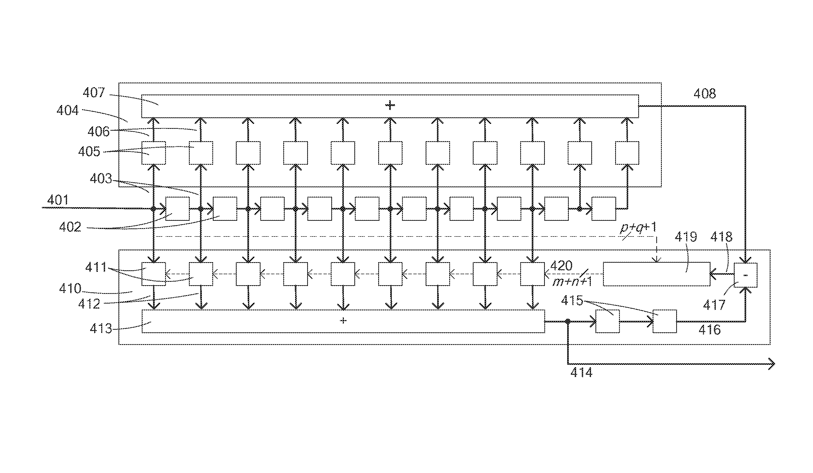
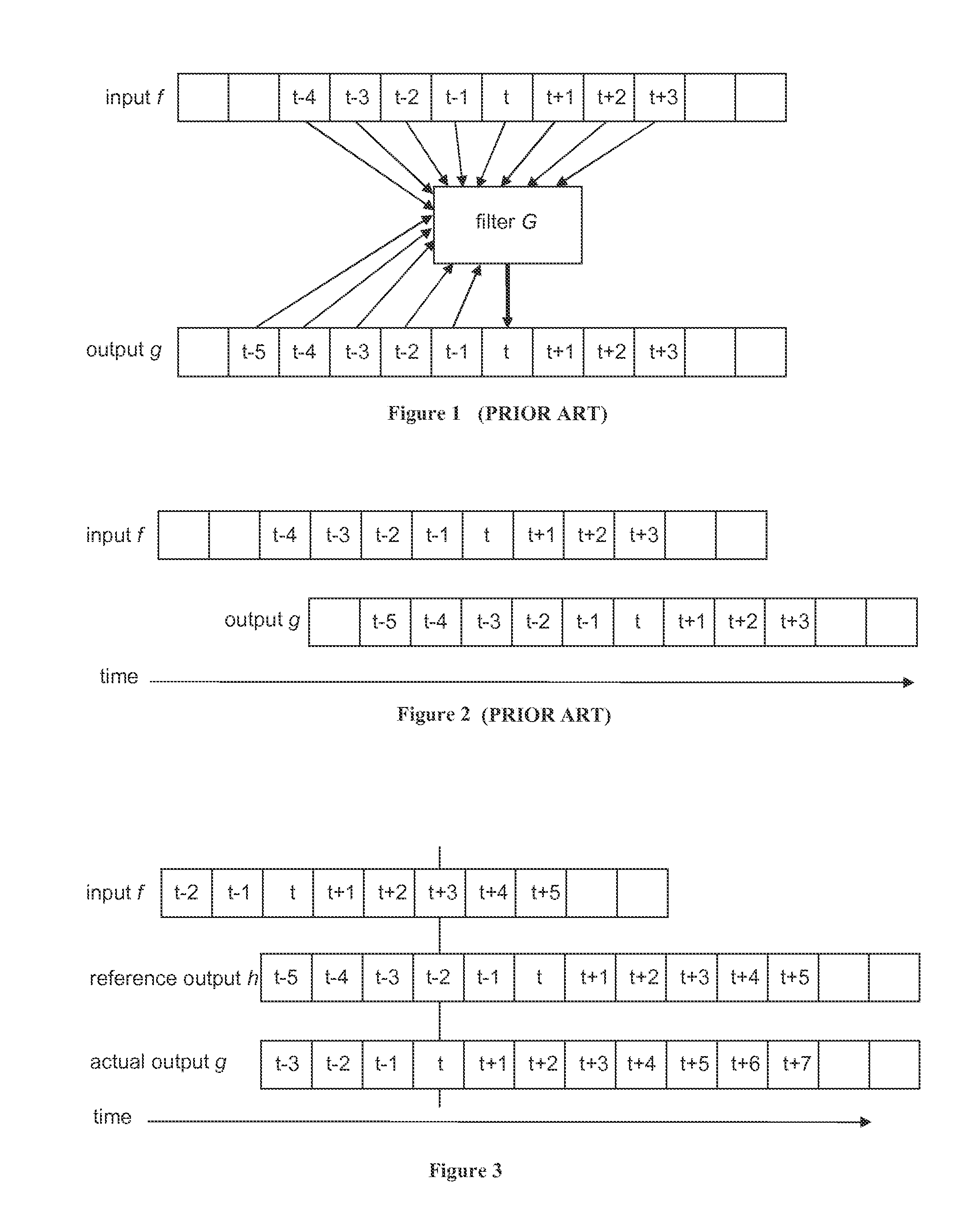
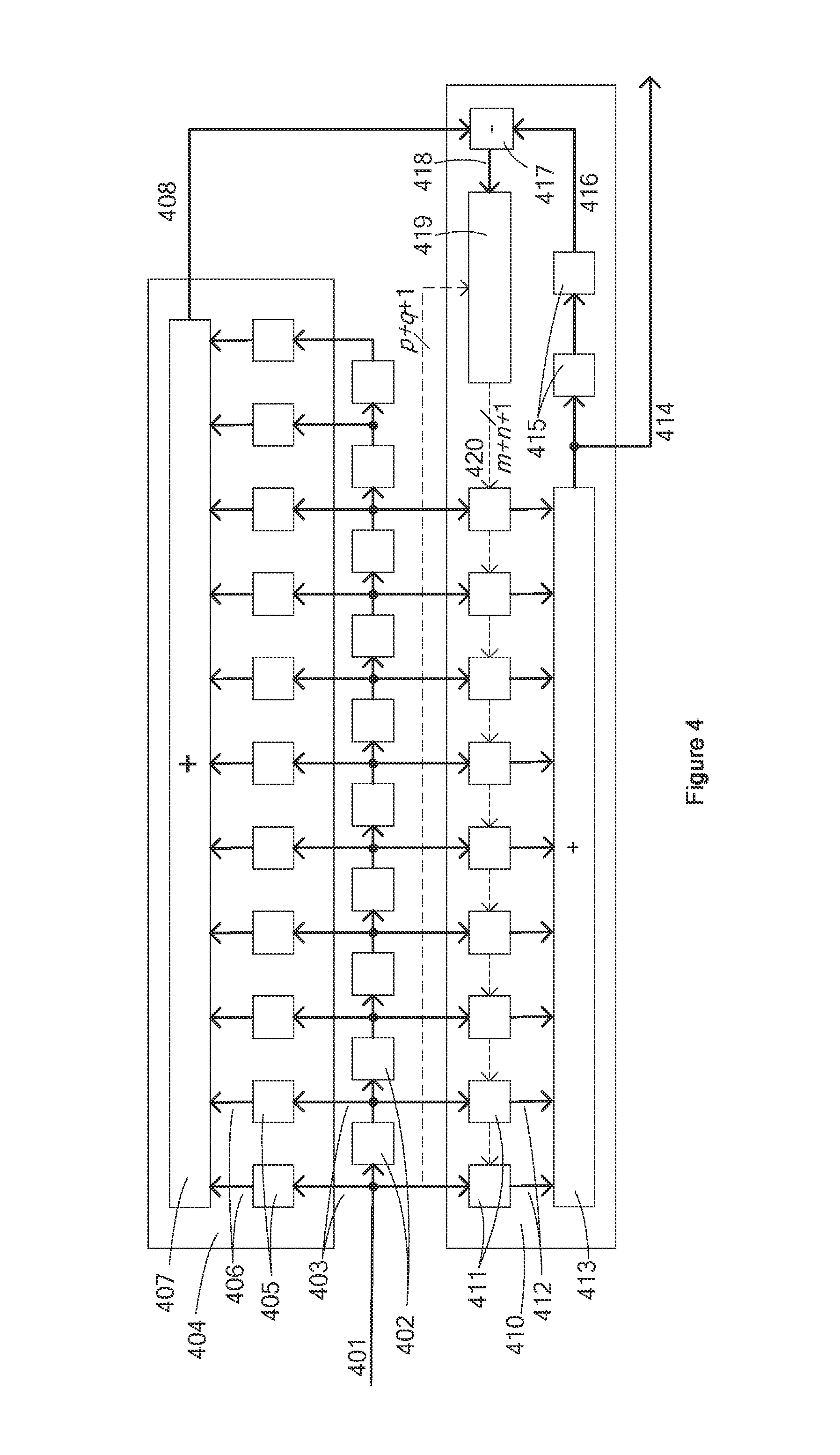
[0029]In an adaptive filter according to the invention the coefficients of the filter are adapted in order to minimize a measure of the error between its output and that of a reference filter of higher latency. An illustration of the relative timings of the input signal, the reference filter output and the adaptive filter output is given in FIG. 3. In this example, the latency of the reference filter is 5 and the latency of the adaptive filter is 3. A block diagram of a suitable system is shown in FIG. 4.

[0030]The exemplary process operates on a sampled-signal filter; however the skilled person will appreciate that analogous processing can be carried out on filters operating on non-sampled analogue signals.

[0031]Referring to FIG. 4, input data (401) is passed through a series of delay elements (402) whose outputs (403) are applied to a reference filter (404). The reference filter (404) consists of a set of coefficients (405) which are multiplied by the respective delayed input signa...


PUM


Abstract

An adaptive low pass filtering process with a filter delay DA is conducted in parallel with reference low pass filtering process with a filter delay DR which is greater than DA. The error is measured between a delayed version of the adaptive process output and the reference process output. Filter parameters of the adaptive process are controlled to minimize the error.

Description

FIELD OF INVENTION[0001]This invention concerns processing of signals in applications where it is important to achieve a low latency or pipeline delay through the process.BACKGROUND OF THE INVENTION[0002]In real-time sampled-signal processing such as digital filtering, each output sample depends typically on a number of input samples and, in the case of recursive processing such as infinite impulse response (IIR) filtering, additionally on past output samples. In most applications there will be a correspondence in time between input samples and output samples. For example, an event in the input signal that is preserved by the process would be considered to be contemporaneous with the corresponding event in the output signal. In many cases it is desirable that the process has access to input samples both in the past and in the future. However, since a causal system cannot in reality access future samples, the process has to wait until the last required input sample has arrived before...

Claims


Application Information

Patent Timeline
Patent Type & Authority Patents(United States)
IPC IPC(8): G06F17/10H03H21/00
CPCH03H21/0012H04N5/21H04N5/2628
Inventor KNEE, MICHAEL JAMES
Owner GRASS VALLEY LTD
Why Eureka
Try Eureka