
Angle sensor

a sensor and angle technology, applied in the field of angle sensors, can solve problems such as and achieve the effects of minimizing the error in the measurement value, minimizing the value of scale factor, and minimizing the error in the measurement of the rotation amoun

Active Publication Date: 2012-06-21
LG INNOTEK CO LTD
View PDF7 Cites 1 Cited by
  • Summary
  • Abstract
  • Description
  • Claims
  • Application Information

AI Technical Summary

Benefits of technology

[0013]Accordingly, the present invention has been made keeping in mind the above problems occurring in the prior art, and an object of the present invention is to provide an angle sensor, which is capable of minimizing an error in measuring rotation of a steering shaft by selecting an optimum gear ratio between main and subsidiary gears of the angle sensor.
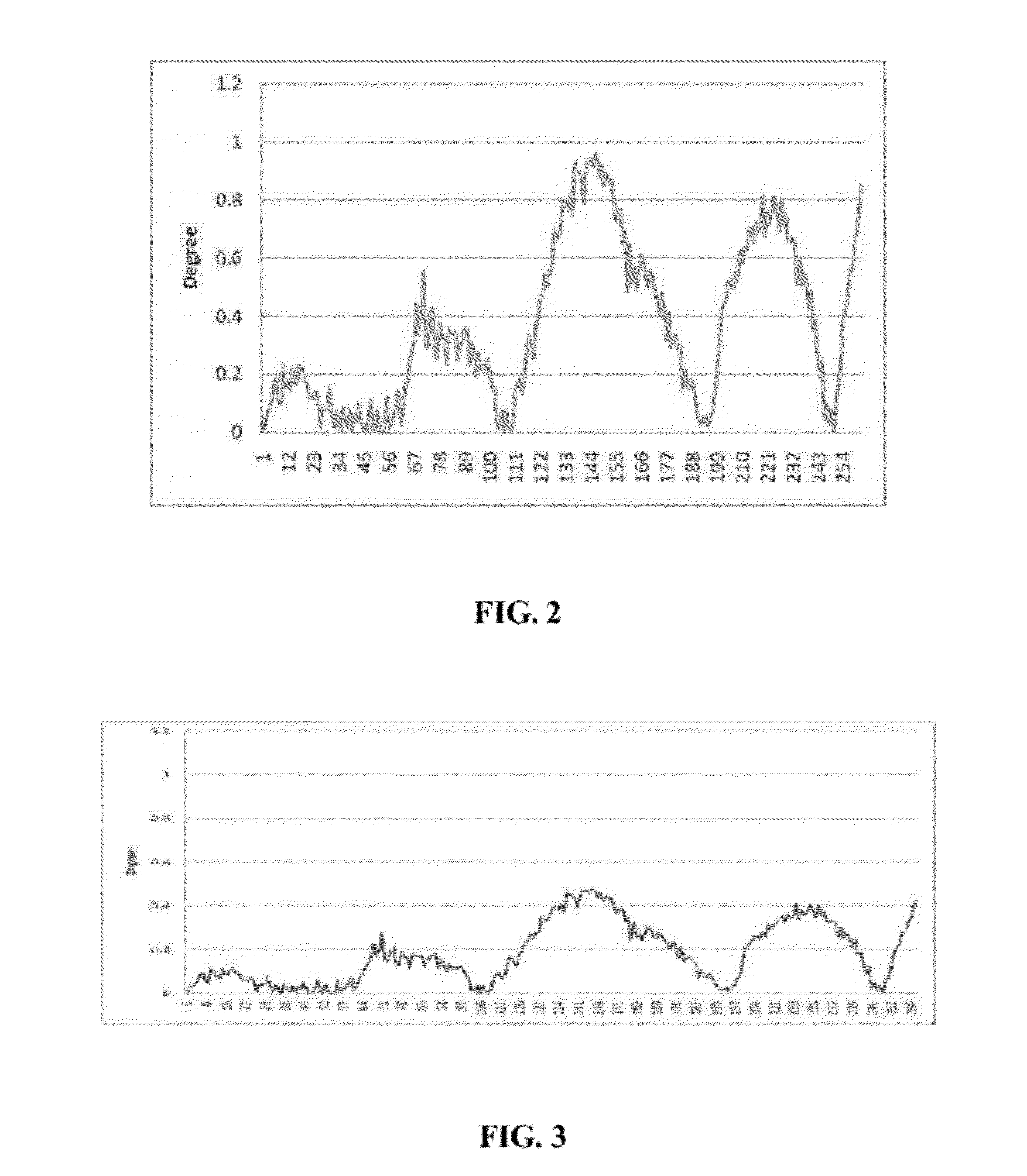
[0014]According to one aspect of this invention, there is provided an angle sensor which measures a rotation amount of a vehicle steering shaft and includes a ring-shaped main gear rotating along with the steering shaft, a first subsidiary gear rotated by rotation of the main gear and having a magnet coupled to a surface thereof, and a magnetic device detecting a change in magnetic field of the magnet and outputting data on a rotation amount, so that the first subsidiary gear rotates four times while the main gear rotates once. Therefore, the angle sensor is advantageous in that a value of scale factor is minimized while valid data for measuring an angle of the main gear is acquired, so that an error in the measured value is minimized.
[0015]The angle sensor further includes a second subsidiary gear engaging with the main gear, wherein the first subsidiary gear engages with the second subsidiary gear, and a gear ratio of the main gear to the first subsidiary gear is 4:1. Therefore, the angle sensor is advantageous in that high sensitivity to a change in magnetic field is achieved and nonlinearity of data on the measured value is improved.
[0016]Further, the magnetic device comprises a Hall IC. Therefore, the angle sensor is advantageous in that an output signal can be efficiently analyzed by a change in magnetic field.
[0017]As apparent from the above description, the angle sensor according to the present invention is advantageous in that an optimum gear ratio is set between the main and subsidiary gears, so that an error ratio of the magnetic device is reduced without lowering detection efficiency for a change in magnetic field, thus increasing nonlinearity of output data, and enabling precise angle measurement.

Problems solved by technology

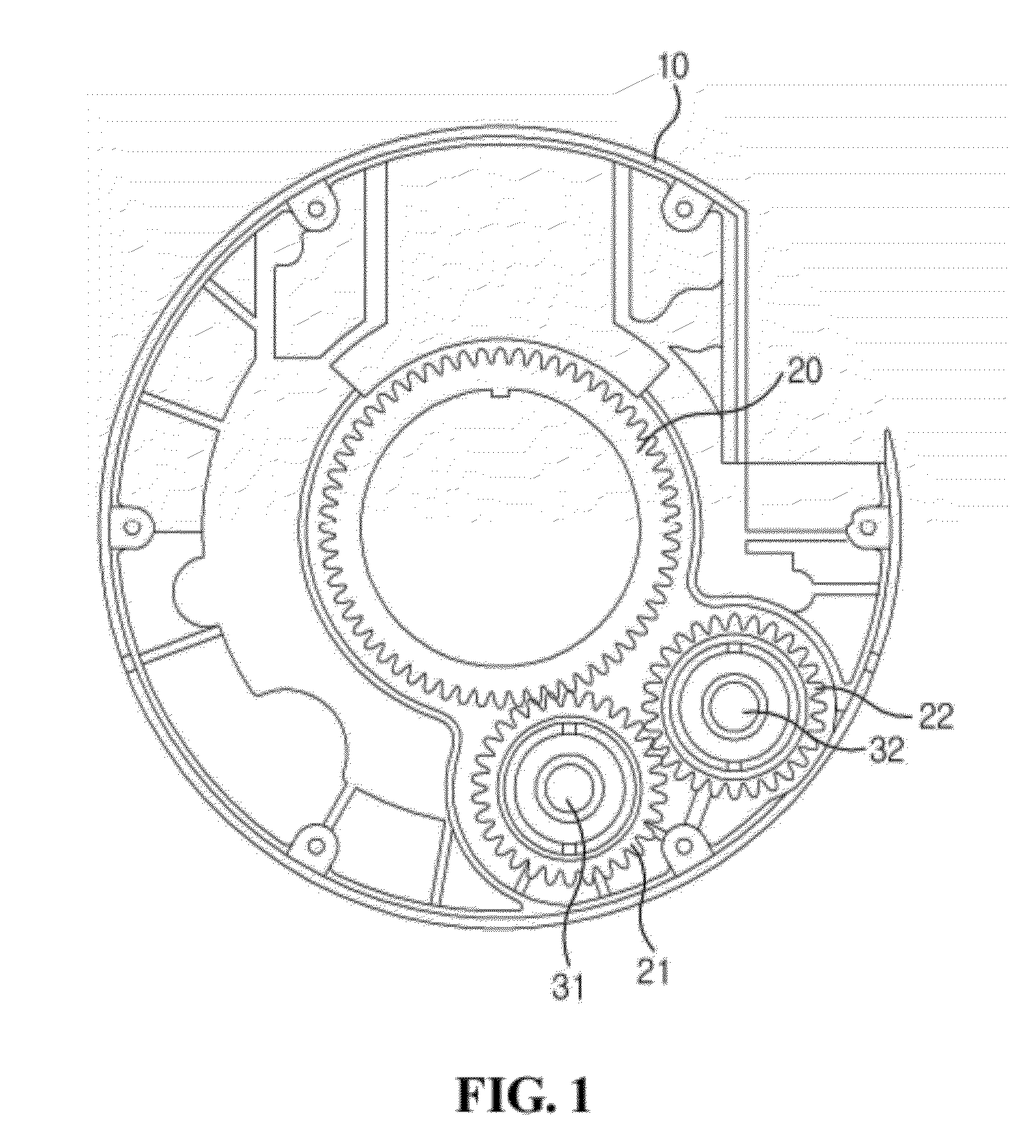
Consequently, the conventional angle sensor is problematic in that a value of the scale factor is large, so that an error in measurement of a rotation amount occurs.

Method used


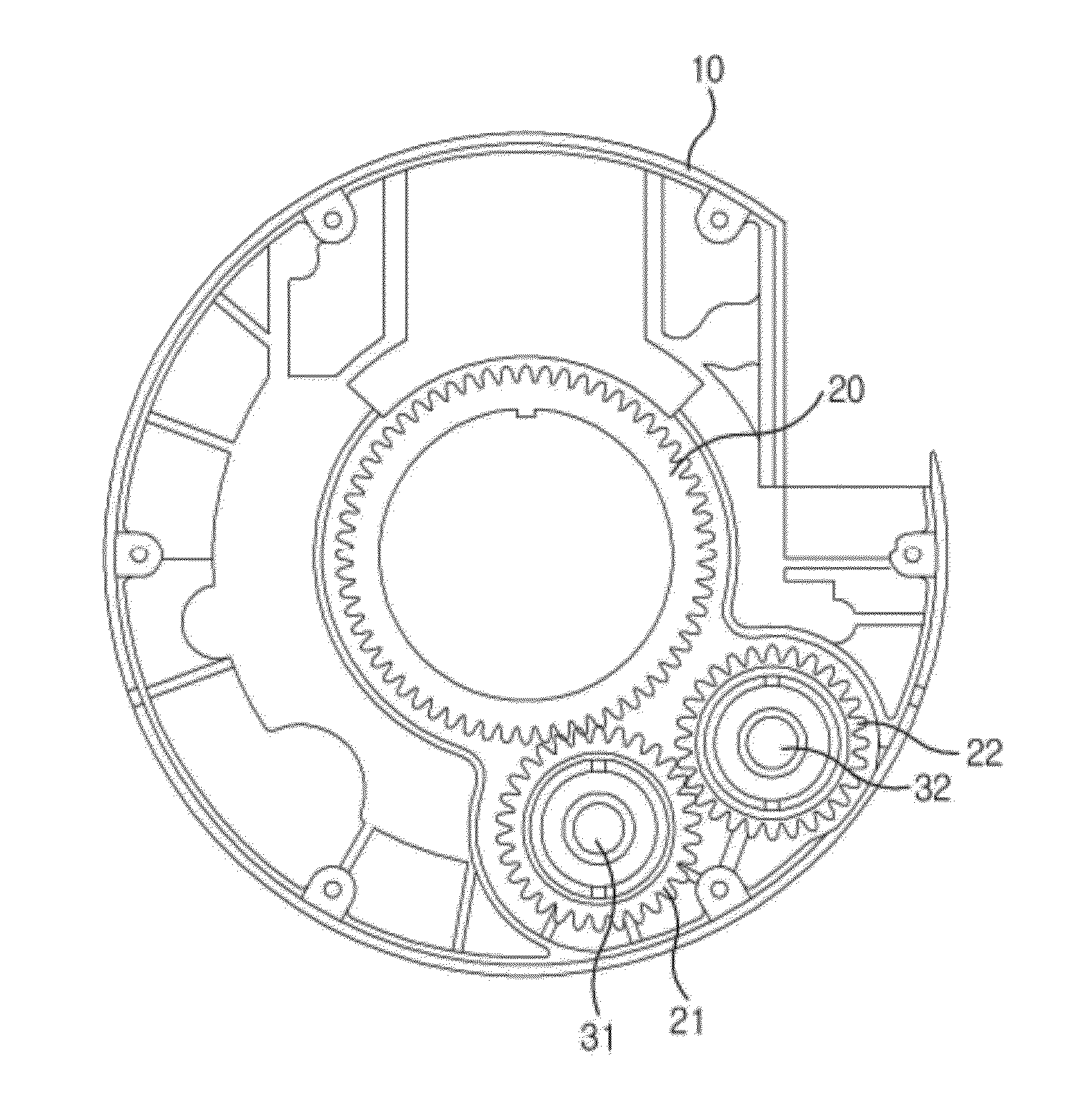
Image

  • Angle sensor
  • Angle sensor
  • Angle sensor

Examples


Embodiment Construction

[0021]An angle sensor according to a preferred embodiment of the present invention will be described below in detail with reference to the accompanying drawings.

[0022]Hereinafter, the angle sensor according to the present invention will be described with reference to the construction of the angle sensor shown in FIG. 1.

[0023]Further, the angle sensor includes a ring-shaped main gear 20 rotating along with a steering shaft of a vehicle, a second subsidiary gear 21 engaging with the main gear 20, and a first subsidiary gear 22 engaging with the second subsidiary gear 21.

[0024]The gears 20, 21, and 22 are rotatably coupled to one surface of a casing 10. The casing 10 approximately takes a shape of a disc, and an opening is formed in a central portion of the casing 10 to correspond to a hollow portion of the main gear 20.

[0025]The steering shaft of the vehicle is connected to a central portion of the main gear 20 to rotate along therewith.

[0026]As the main gear 20 rotates, the second su...


PUM


Abstract

Disclosed is an angle sensor, which is capable of accurately measuring an angle of a steering shaft by selecting an optimum gear ratio between main and subsidiary gears constituting the angle sensor, measures a rotation amount of a vehicle steering shaft, and includes a ring-shaped main gear rotating along with the steering shaft, a first subsidiary gear rotated by rotation of the main gear and having a magnet coupled to a surface thereof, and a magnetic device detecting a change in magnetic field of the magnet and outputting data on a rotation amount, so that the first subsidiary gear rotates four times while the main gear rotates once, and a value of a scale factor is minimized during a process of acquiring valid data for measuring the angle of the main gear and thereby an error of a measured value is minimized.

Description

CROSS-REFERENCE TO RELATED APPLICATION[0001]This application claims the benefit under 35 U.S.C. §119 of Korean Patent Application No. 10-2010-0131195, filed Dec. 21, 2010, which is hereby incorporated by reference in its entirety.BACKGROUND[0002]1. Field of the Invention[0003]The present invention relates generally to an angle sensor and, more particularly, to an angle sensor, which is capable of accurately measuring an angle of a steering shaft by selecting an optimum gear ratio between main and subsidiary gears constituting the angle sensor.[0004]2. Description of the Related Art[0005]Generally, an auxiliary steering system supported by additional power is used as a device for ensuring the steering stability of a vehicle. Conventionally, the auxiliary steering system uses a hydraulic pressure. However, recently, an electronic power steering system, which consumes less power and is excellent in accuracy, has been used[0006]Such an electronic power steering system (EPS) drives a mot...

Claims


Application Information

Patent Timeline
Patent Type & Authority Applications(United States)
IPC IPC(8): G01B7/30
CPCB62D15/0215G01D5/145B62D15/0245G01D2205/26
Inventor SHIN, SUNGCHUL
Owner LG INNOTEK CO LTD
Learn More