Method and system for adjusting a circuit symbol

a circuit symbol and symbol technology, applied in the field of computer-aided circuit design, can solve problems such as loss of connectivity, problems relating to different positions, and problems, and achieve the effect of minimizing an error measuremen

Inactive Publication Date: 2017-10-10
GLOBALFOUNDRIES U S INC
View PDF8 Cites 2 Cited by
  • Summary
  • Abstract
  • Description
  • Claims
  • Application Information

AI Technical Summary

Benefits of technology

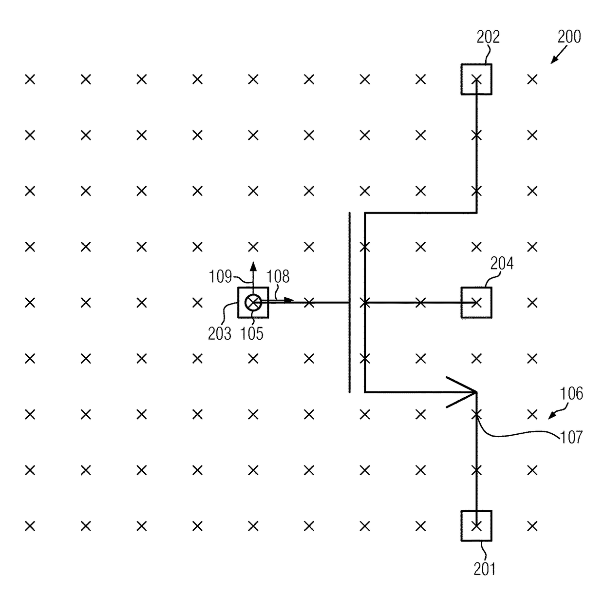
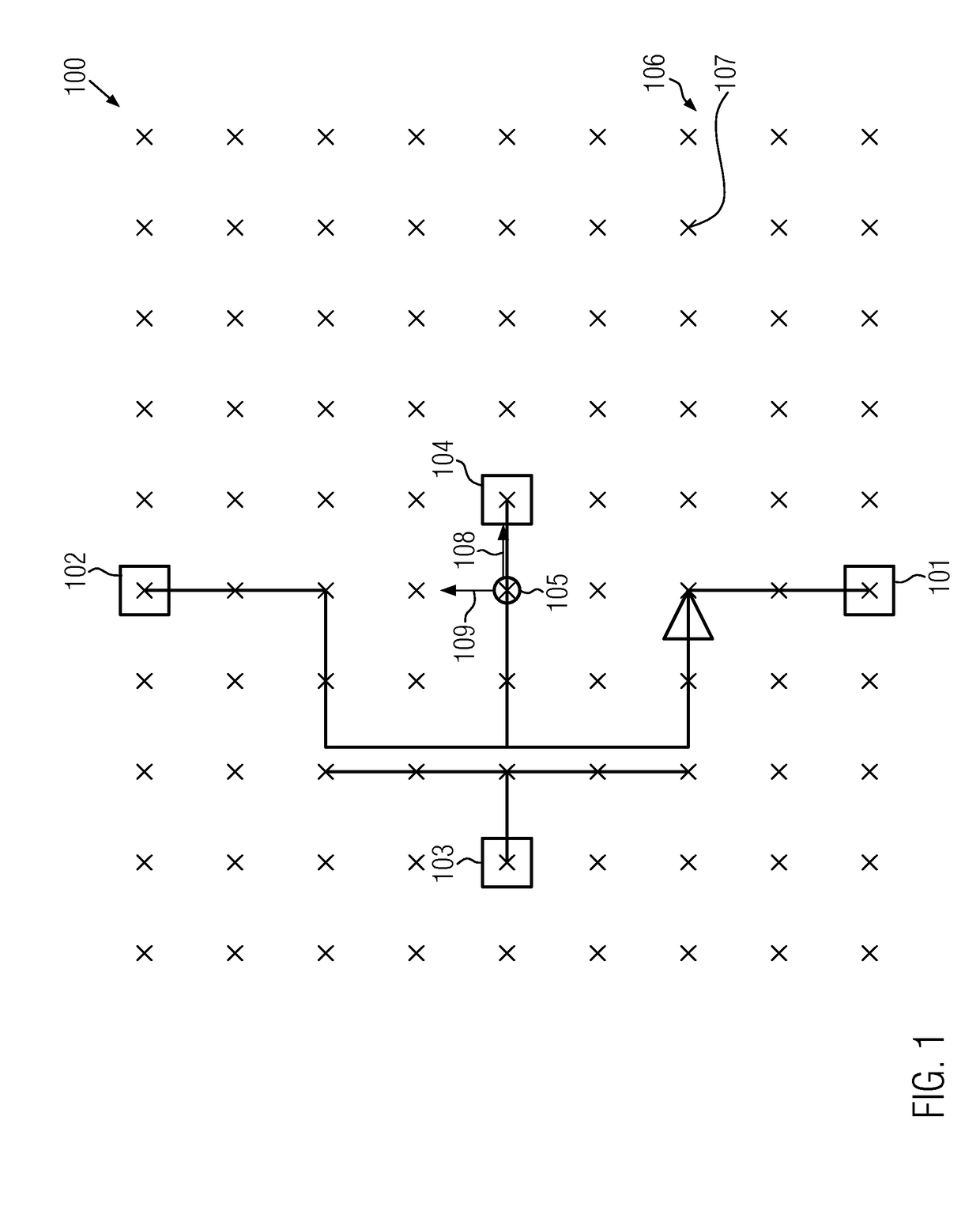
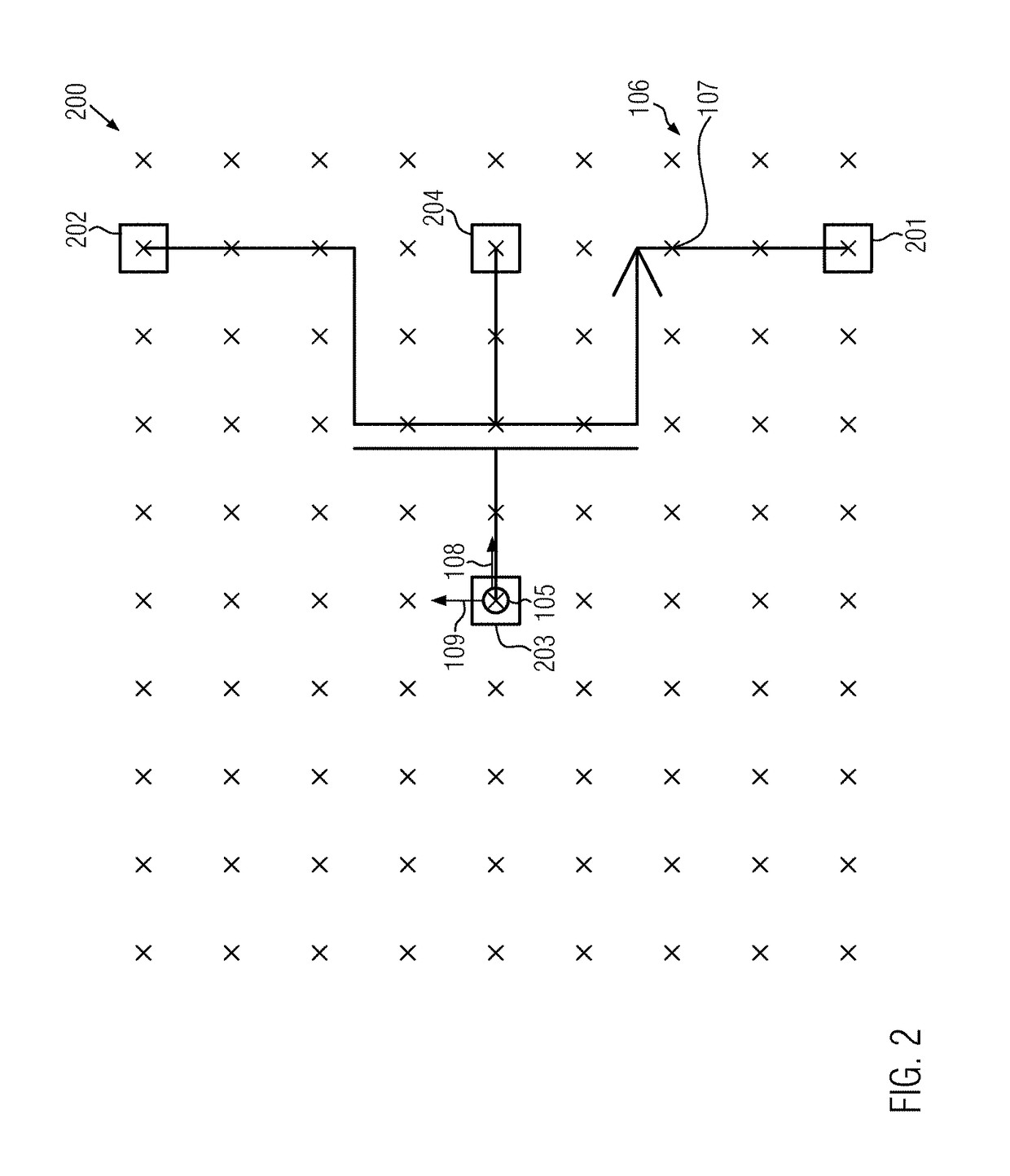
[0019]An illustrative computer-readable storage medium described herein includes code for causing a computer to obtain first data, to obtain second data, and to determine an adjustment transformation. The first data represent a first circuit symbol. The first circuit symbol has a plurality of first pins. Each first pin has a first position vector associated therewith. The second data represent a second circuit symbol. The second circuit symbol has a plurality of second pins. Each of the plurality of second pins has a second position vector associated therewith. Each of the plurality of second pins corresponds to a respective one of the plurality of first pins. The adjustment transformation maps position vectors to transformed position vectors. The adjustment transformation minimizes an error measure that is based on one or more deviations. Each deviation is a deviation between a transformed position vector and the first position vector associated with one of the first pins. The transformed position vector is obtainable by applying the adjustment transformation to the second position vector associated with the second pin corresponding to the first pin.

Problems solved by technology

When a circuit schematic is to be converted from a first process design kit to a second process design kit, for example from a process design kit wherein proprietary circuit symbols are used to a process design kit wherein standard circuit symbols, such as circuit symbols in accordance with the OpenPDK V1.0 Standard, are used, issues can occur which can, in particular, be related to different positions of pins.
Since, as described above, positions of pins can be relevant for determining the connection of devices, replacing circuit symbols from the first process design kit with circuit symbols from the second process design kit having different pin positions can lead to a loss of connectivity.
Known methods for converting circuit schematics from a first process design kit to a second process design kit typically rely on empirical user-defined mapping files or similar lookup mechanisms, the provision of which can require a relatively large amount of work.

Method used


Image

  • Method and system for adjusting a circuit symbol
  • Method and system for adjusting a circuit symbol
  • Method and system for adjusting a circuit symbol

Examples


Embodiment Construction

[0033]Various illustrative embodiments of the invention are described below. In the interest of clarity, not all features of an actual implementation are described in this specification. It will of course be appreciated that in the development of any such actual embodiment, numerous implementation-specific decisions must be made to achieve the developers' specific goals, such as compliance with system-related and business-related constraints, which will vary from one implementation to another. Moreover, it will be appreciated that such a development effort might be complex and time-consuming, but would nevertheless be a routine undertaking for those of ordinary skill in the art having the benefit of this disclosure.

[0034]The present disclosure will now be described with reference to the attached figures. Various structures, systems and devices are schematically depicted in the drawings for purposes of explanation only and so as to not obscure the present disclosure with details whic...


PUM


Abstract

A method includes obtaining first data representing a first circuit symbol and second data representing a second circuit symbol. The first circuit symbol has a plurality of first pins having a first position vector associated therewith. The second circuit symbol has a plurality of second pins having a second position vector associated therewith, and each of the plurality of second pins corresponds to a respective one of the plurality of first pins. An adjustment transformation mapping position vectors to transform the position vectors is determined. The adjustment transformation minimizes an error measure that is based on one or more deviations. Each deviation is a deviation between a transformed position vector and the first position vector associated with one of the first pins. The transformed position vector is obtained by applying the adjustment transformation to the second position vector associated with the second pin corresponding to the first pin.

Description

BACKGROUND OF THE INVENTION[0001]1. Field of the Invention[0002]Generally, the present disclosure relates to the computer-aided design of circuits, and, more particularly, to methods and systems that may be used in the context of a replacement of first circuit symbols in a circuit schematic with second circuit symbols.[0003]2. Description of the Related Art[0004]In the computer-aided design of electronic circuits, electronic design automation tools may be used. Electronic design automation tools may be provided in the form of software that includes instructions that can be carried out by a computer for processing data representing circuit schematics. The circuit schematics can include circuit symbols that represent circuit elements such as, for example, transistors, diodes, resistors, capacitors and inductivities. Additionally, the circuit schematics can include wires that represent electrical connections between the circuit elements.[0005]The data representing a circuit schematic c...

Claims


Application Information

Patent Timeline
Patent Type & Authority Patents(United States)
IPC IPC(8): G06F17/50
CPCG06F17/5081G06F17/5072G06F30/39G06F30/20G06T11/203G06F30/398G06F30/30G06F30/392
Inventor JUMMEL, GUNTRAM
Owner GLOBALFOUNDRIES U S INC
Why Eureka
Try Eureka