
Modular, self supporting exterior enclosure system with insulating, evacuated tubes having solar collector rods

a solar collector and module technology, applied in the direction of solar radiation prevention, heat collector mounting/support, light and heating apparatus, etc., can solve the problems of increasing heating and cooling requirements, reducing the efficiency of solar energy generation, so as to reduce or eliminate conductive and convective heat transfer and eliminate solar heat loads

Active Publication Date: 2015-04-14
SKIDMORE OWINGS & MERRILL LLP
View PDF17 Cites 22 Cited by
  • Summary
  • Abstract
  • Description
  • Claims
  • Application Information

AI Technical Summary

Benefits of technology

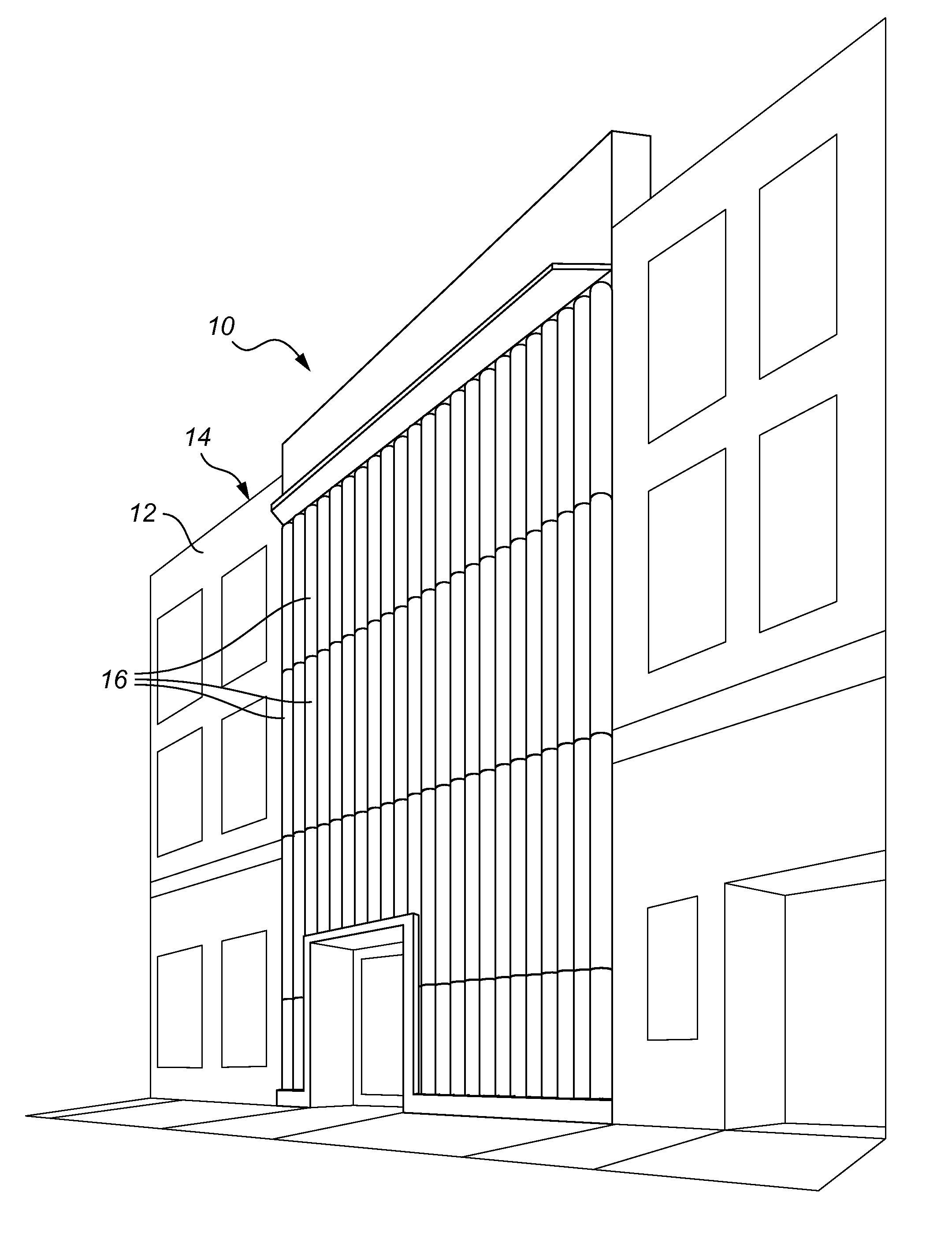
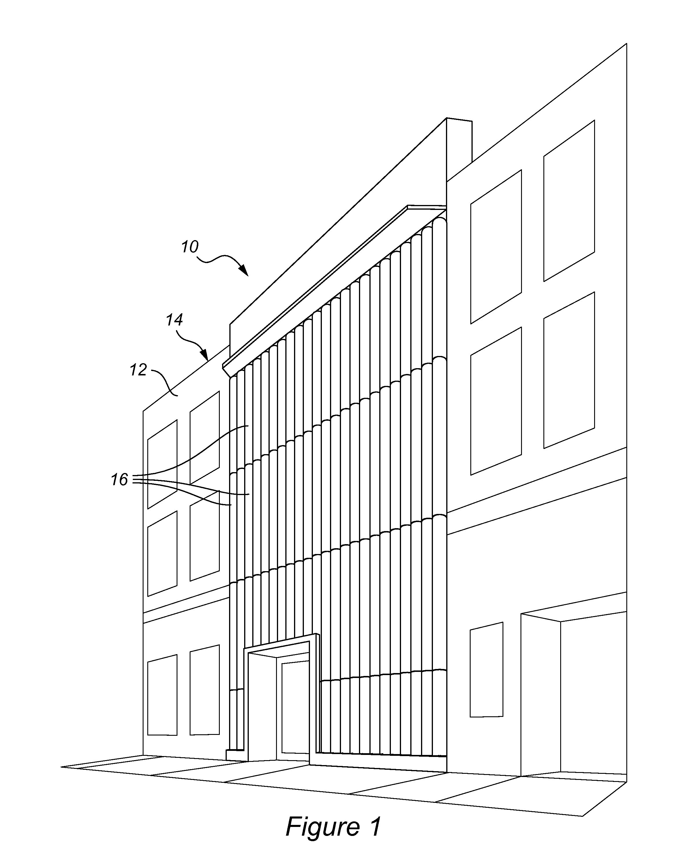
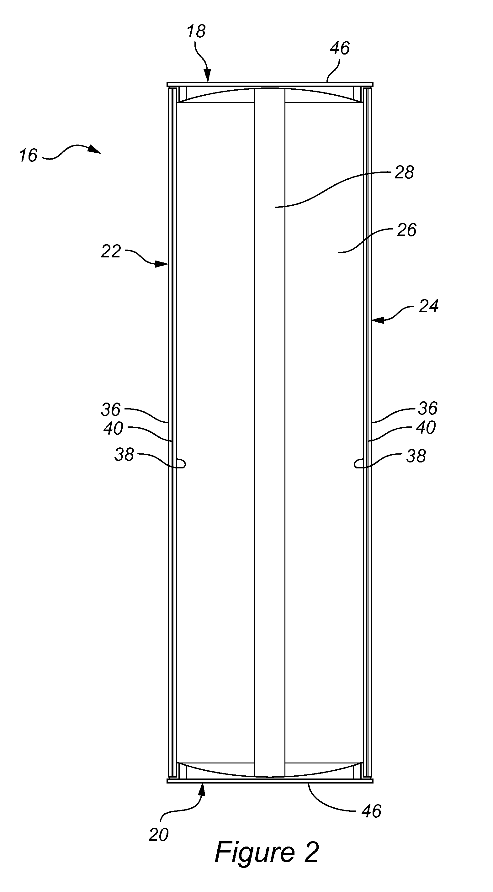
[0013]The system of the present inventive concept is self-supporting due at least in part to a structural depth of each of the tubular glass units. Geometrical properties of the tubular glass units also maintain an airless or vacuum chamber without any additional structural support. The vacuum chamber advantageously significantly reduces or eliminates conductive and convective heat transfer through the tubular glass units, thereby allowing the system to provide a thermal buffer or insulator for both hot and cold climates. Each of the tubular glass units includes a convex outer half glass-lite configured to refract and focus incoming solar radiation to an approximate center of the chamber, thereby concentrating the energy to a focal point and enabling a solar collector positioned at or near the center to generate power. In this manner, the system is configured to extract solar power radiating partially through the glass tubes while eliminating solar heat loads.
[0014]In its simplest form, the system of the present inventive concept includes a grid of independently attached, interconnected units. Each of the units are pre-fabricated in a controlled shop environment from a kit of uniform, custom-fabricated components. Each of the units is constructed of two curved pieces of laminated glass having a uniform or non-uniform radius, thermally-broken metal, e.g., aluminum extrusion, or other like material of sufficient strength, and plate framing, structural and weather seals and gaskets, setting hardware and stainless steel trim. The system includes a sub-structural suspension network with each of the units precisely placed and secured in repeating rows and columns. The components of each unit, i.e., their perimeter detailing, seal each of the units against each other to create a building enclosure. Each of the units includes an interior void enclosed by a plurality of walls of which at least one is configured to allow light incident thereon to at least partially pass therethrough. Each of the units houses at least a portion of a solar energy photovoltaic rod positioned at a focal point at an approximate center of an interior void. The focal point is defined by the at least one wall. The system provides a building enclosure with a fully glazed facade having an R-value comparable to an insulated solid wall. The system is configured to be assembled in connection with any building type. The system, via each of the units, is configured to create translucency and / or opacity to permit versatility for various designs.

Problems solved by technology

Conventional building enclosures suffer from a number of problems, particularly enclosures equipped with windows or glazed portions.
Undesirable ambient energy transfer is highest on glazed portions of the enclosures.
Such energy transfer results in increased heating and cooling requirements to maintain an enclosed interior space at a desired temperature.
In attempt to reduce ambient energy transfer, designs for enclosures may limit the exposed area of glazed portions.
Each of these options, however, includes undesirable effects.
Reducing the exposed area of glazed portions limits views to an exterior environment of the enclosures, which is undesirable to inhabitants and other users.
Further, it reduces or eliminates the amount of natural light that is allowed to enter the enclosure, thereby increasing demand for artificial lighting to illuminate the interior of enclosures, which results in increased energy consumption.
Artificial light is also undesirable because it is typically of poor quality, e.g., has a poor color rendition index relative to natural light.
Such flat glass is susceptible to bowing from pressure exerted by the lack of air in the interior.
Additionally, flat glass is not self-supporting and requires additional structural support upon assembly.
The Hermann tubes are manufactured as extruded glass, which necessarily includes undesirable manufacturing limitations when large diameters and / or long lengths are required for an application.
The Hermann disclosure also fails to provide a workable structure for arranging or supporting the tubes for use in a variety of challenging structural settings.
Further, the Hermann tubes do not independently seal an enclosure or form a thermal break and, therefore, require additional material in the form of supplemental panes of glass.

Method used


Image

  • Modular, self supporting exterior enclosure system with insulating, evacuated tubes having solar collector rods
  • Modular, self supporting exterior enclosure system with insulating, evacuated tubes having solar collector rods
  • Modular, self supporting exterior enclosure system with insulating, evacuated tubes having solar collector rods

Examples


Embodiment Construction

[0040]The following detailed description references the accompanying figures that illustrate the present inventive concept. The illustrations and description are intended to describe aspects of the present inventive concept in sufficient detail to enable those skilled in the art to practice the present inventive concept. Other components can be utilized and changes can be made without departing from the scope of the present inventive concept. The following detailed description is, therefore, not to be taken in a limiting sense. The scope of the present inventive concept is defined only by the appended claims, along with the full scope of equivalents to which such claims are entitled.

[0041]In this description, references to an “embodiment” or “embodiments” mean that the feature or features being referred to are included in at least one embodiment of the present inventive concept. Separate references to an “embodiment” or “embodiments” do not necessarily refer to the same embodiment a...


PUM


Abstract

A tubular building enclosure system with thermally-broken modules having evacuated air spaces assembled in rows and / or columns to form a structurally self-supporting, thermally insulating, and solar energy collecting facade.

Description

CROSS-REFERENCE TO RELATED APPLICATION[0001]This Patent Application claims priority to U.S. patent application Ser. No. 14 / 015,071 titled Modular, Self Supporting Exterior Enclosure System With Insulating, Evacuated Tubes Having Solar Collector Rods, and filed Aug. 30, 2013, the entire contents of which are herein incorporated by reference in its entirety.BACKGROUND OF THE INVENTION[0002]1. Field of the Invention[0003]The present invention relates to static building structures, and more particularly, to a tubular enclosure system configured to control an interior environment thereof and convert solar radiation to electricity, and to methods of erecting and using the system.[0004]2. Description of Related Art[0005]Conventional building enclosures suffer from a number of problems, particularly enclosures equipped with windows or glazed portions. Undesirable ambient energy transfer is highest on glazed portions of the enclosures. Such energy transfer results in increased heating and co...

Claims


Application Information

Patent Timeline
Patent Type & Authority Patents(United States)
IPC IPC(8): E04D13/18E04B2/88F24J2/46F24J2/51F24J2/52F24S10/40F24S23/30F24S90/00H01L31/048H01L31/054H02S20/26
CPCH02S20/26F24J2/5201F24J2/42F24J2/464F24J2/51F24J2/465F24J2/5245E04B2/88H01L31/0543H01L31/048F24J2002/5215E04F13/0871E04F13/0898E04F13/145H02S20/20E04F13/0733F24S10/45F24S23/30F24S25/61F24S25/65F24S80/54F24S20/66Y02B10/20Y02E10/47Y02E10/44Y02B10/10Y02E10/52
Inventor ASCI, AYBARSHANEY, GARYRAINEY, TERESAOLSEN, CHRISTOPHERBOONE, ELIZABETH
Owner SKIDMORE OWINGS & MERRILL LLP
Learn More