Aerodynamic mud flap

a technology of aerodynamic mud flaps and motor vehicles, which is applied in the direction of vehicle components, deflectors, superstructure subunits, etc., can solve the problems of reducing the fuel efficiency of the vehicle, adding weight to the vehicle, and premature wear

Active Publication Date: 2015-04-14
STREETCAREC SLOAN
View PDF61 Cites 20 Cited by
  • Summary
  • Abstract
  • Description
  • Claims
  • Application Information

AI Technical Summary

Benefits of technology

[0013]In another embodiment, the plate-like body may have an obverse face and an opposed reverse face which have identical recess configuration whereby the obverse and reverse face have symmetry about a parallel plane between them. Further, the plate-like body may have a projecting rib on one face and a recess corresponding to the rib on the other face whereby multiple mud flaps can be stacked with ribs of one mud flap received in a corresponding recess in an overlying mud flap to reduce sliding of stacked mud flaps with respect to each other.

Problems solved by technology

First, such mud flaps tended to sail, lifting the lower portion of the mud flap away from the roadway, thereby enabling water and debris to flow beneath the mud flap and onto windshields of trailing vehicles. Typically anti-sail brackets are mounted to the vehicle behind the mud flaps to restrain the sailing tendency of the mud flaps, thereby adding weight to the vehicle.
Second, solid panel mud flaps are typically heavy and, consequently, can significantly reduce a vehicle's fuel efficiency.
Third, because the flow of air in the region of the wheels can be blocked by solid section mud flaps, the tires, brakes, and bearings can generate high temperatures during use that can lead to failure, premature wear, and reduced service.
Fourth, it can be desirable to utilize a mud flap having a configuration conventionally known as a “shortie,” which can necessitate the costly replacement of a standard mud flap with a “shortie,” or can involve complex modifications to a standard mud flap. Finally, traditional mud flaps tend to atomize water droplets, creating a spray that can affect road visibility for passing and trailing vehicles. Typically, the spray created by the mud flaps migrates around the sides of the mud flap, where it can be projected into the path of other vehicles traveling behind and adjacent the mud flaps.

Method used


Image

  • Aerodynamic mud flap
  • Aerodynamic mud flap
  • Aerodynamic mud flap

Examples


Embodiment Construction

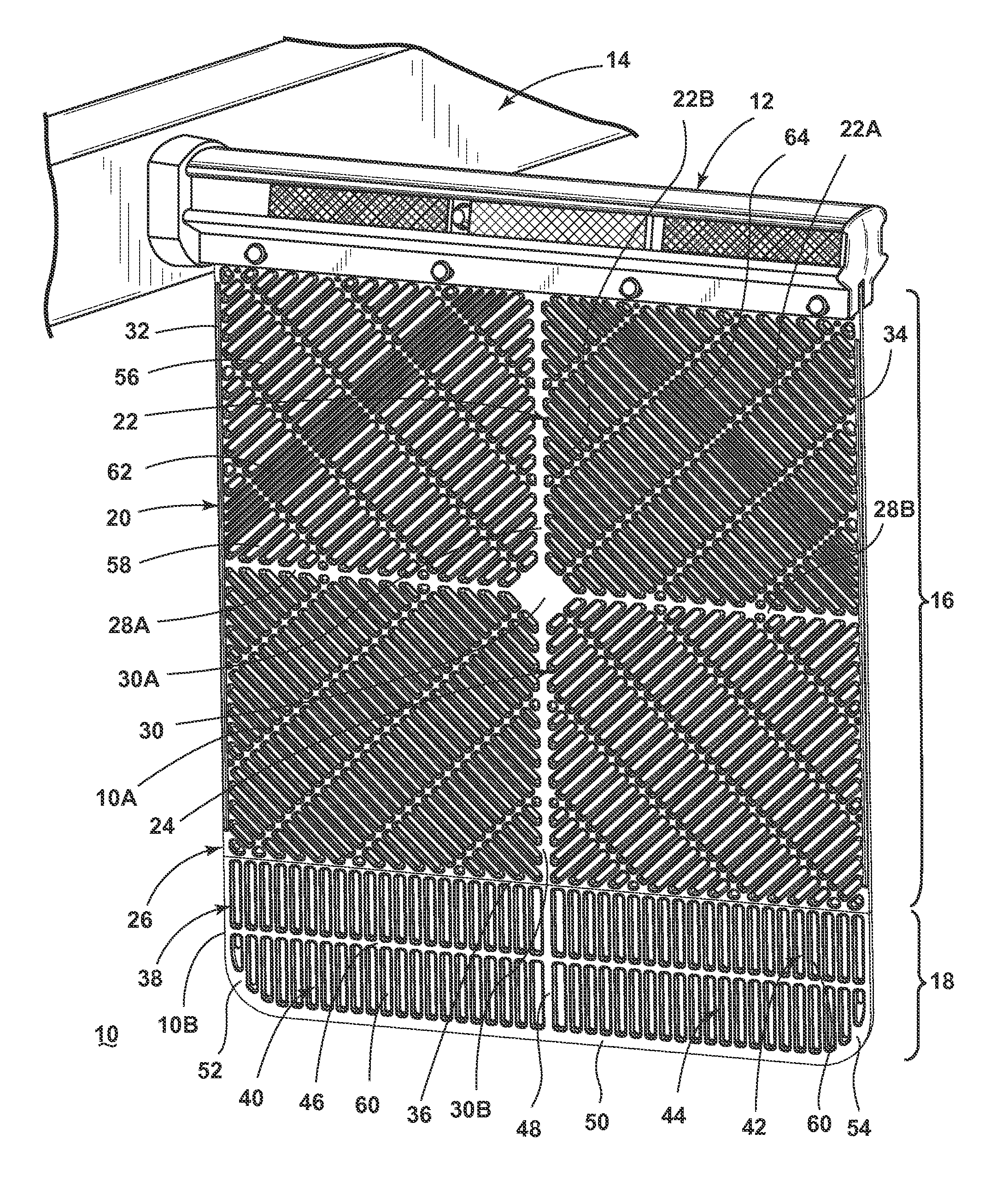
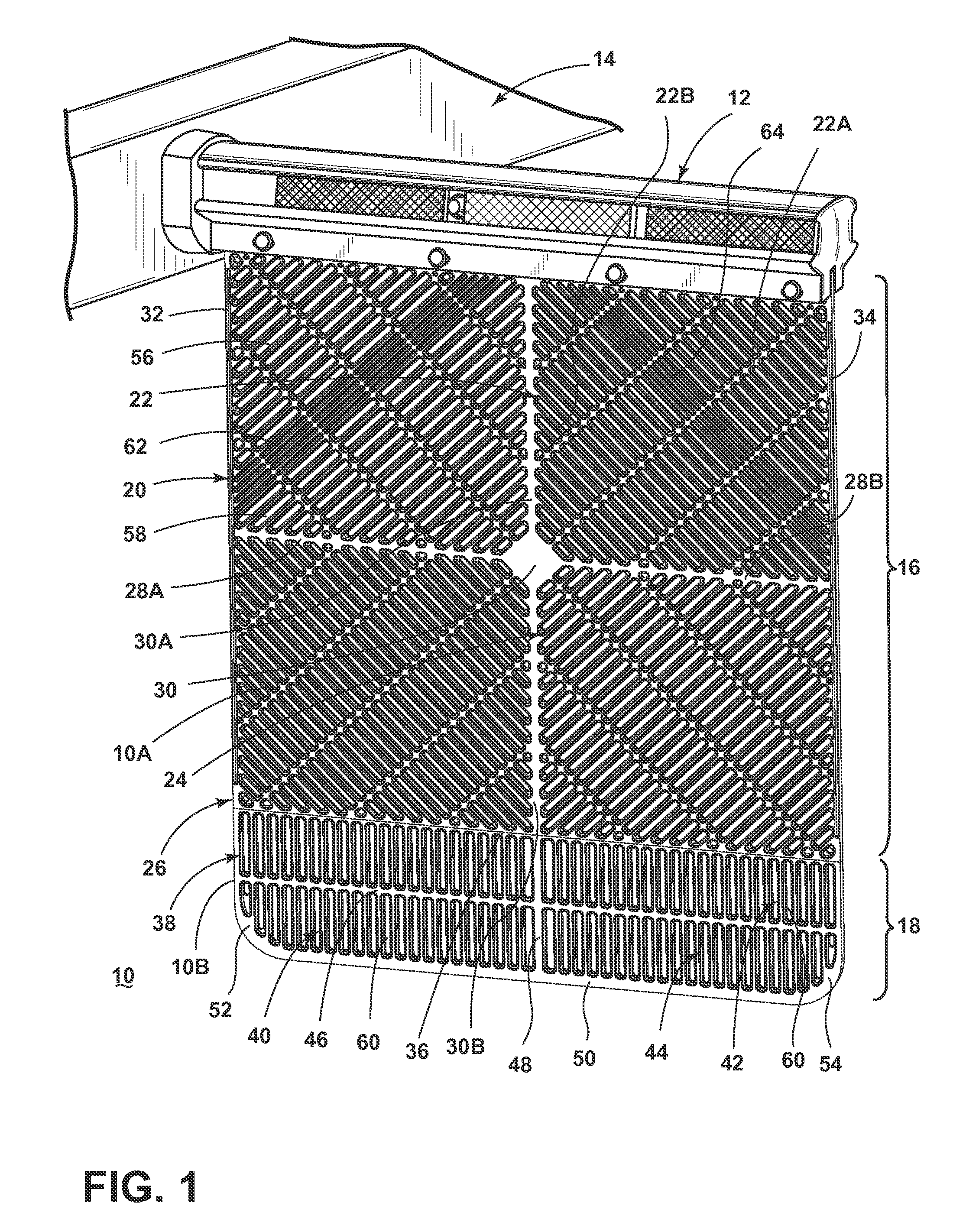
[0023]Referring now to the drawings, and particularly to FIG. 1, an exemplary embodiment of the invention is illustrated comprising a plate-like aerodynamic mud flap 10 having an obverse face 10A and an opposed reverse face 10B. The mud flap 10 can be fabricated of a polymeric material, such as a thermoplastic, and can be fabricated by a suitable injection molding process. Polypropylene is the preferred material for the mud flap. Each face 10A, 10B can have an identical pattern as illustrated in the drawings. The incorporation of identical patterning on each face 10A, 10B means that either face 10A or 10B can face the wheel and can facilitate molding of the mud flap 10. It avoids the necessity of manufacturing a mud flap for each side of the vehicle. This distinction becomes important when manufacturing “Shorty” mud flaps that have an upper outer corner that is removed as illustrated in FIG. 6.

[0024]The nominal thickness, or depth, of the mud flap 10, i.e. the distance separating th...


PUM


Abstract

A motor vehicle mud flap is a plate-like body having a suspension section, a quadrant section, and an extension section. The suspension section is adapted for attachment to a mud flap bracket for suspension of the mud flap therefrom. The quadrant section is coupled with the suspension section and has an array of elongate through-openings. The extension section is coupled with the quadrant section and has an array of elongate through-openings. The array of elongate through-openings is defined by alternating recesses and ribs in parallel and longitudinal disposition. Each recess is configured as a pair of opposed elongate shallow recesses fluidly coupled by an elongate through-opening having a width less than the width of each recess. Water and air can flow through the recesses, and debris larger than the width of the through-openings is deflected by the mud flap.

Description

CROSS-REFERENCE TO RELATED APPLICATION[0001]This application claims the benefit of U.S. Provisional Patent Application No. 61 / 655,693, filed Jun. 5, 2012, which is incorporated herein by reference in its entirety.BACKGROUND OF THE INVENTION[0002]1. Field of the Invention[0003]The invention relates generally to motor vehicle mud flaps. More particularly, the invention relates to a motor vehicle mud flap with aerodynamic properties. In one of its aspects, the invention relates to a mud flap that effectively breaks up trailing air vortex which tends to pull backward out of effective blocking position. In another of its aspects, the invention relates to a mud flap that is adapted to be used with normal or shorty brackets. In another of its aspects, the invention relates to a mud flap that is designed to withstand severe cold temperature. In another of its aspects, the invention relates to a mud flap that stacks neatly and nests on shipping skids for storage and shipping. In another of i...

Claims


Application Information

Patent Timeline
Patent Type & Authority Patents(United States)
IPC IPC(8): B62D25/16B62D25/18
CPCB62D25/18B62D25/188
Inventor EKLUND, WESLEY K.GERST, THOMASROBERTS, GARYHILL, WALTER
Owner STREETCAREC SLOAN
Why Eureka
Try Eureka