
Reflector (optics) used in LED deco lamp

a technology of led lamps and reflectors, which is applied in the direction of semiconductor devices, lighting and heating apparatus, and connection of coupling devices, etc., can solve the problems of reducing the efficiency of use of filaments over time, limiting the widespread use of led lighting systems, and outlasting the life of typical incandescent bulbs. , to achieve the effect of improving the efficiency and light distribution of led lamps

Inactive Publication Date: 2015-04-14
GE LIGHTING SOLUTIONS LLC
View PDF30 Cites 15 Cited by
  • Summary
  • Abstract
  • Description
  • Claims
  • Application Information

AI Technical Summary

Benefits of technology

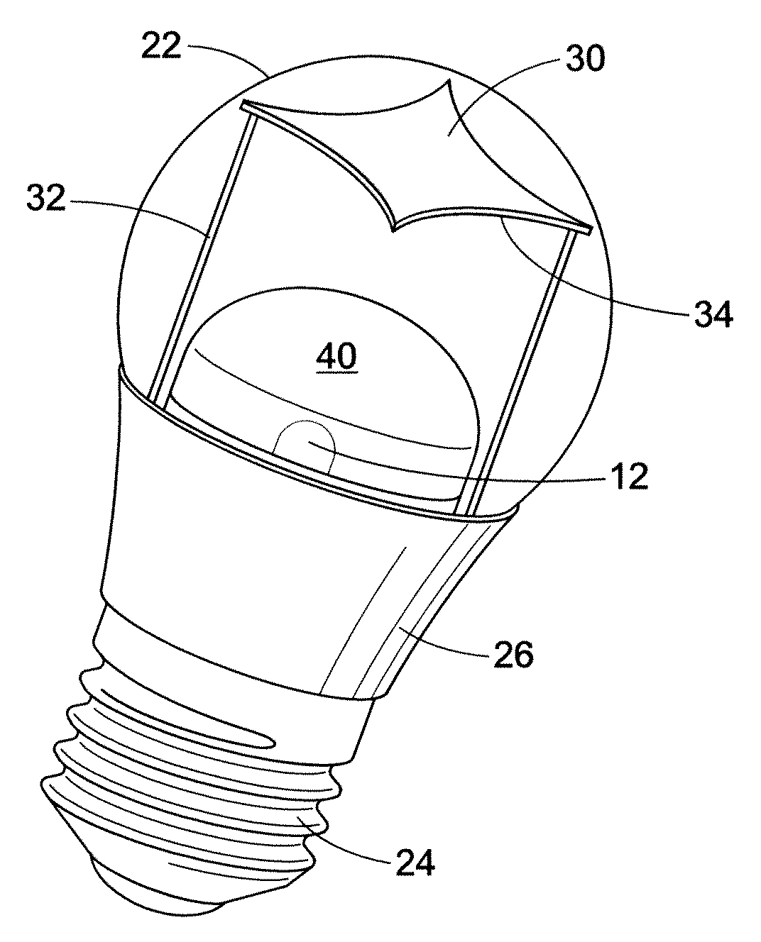
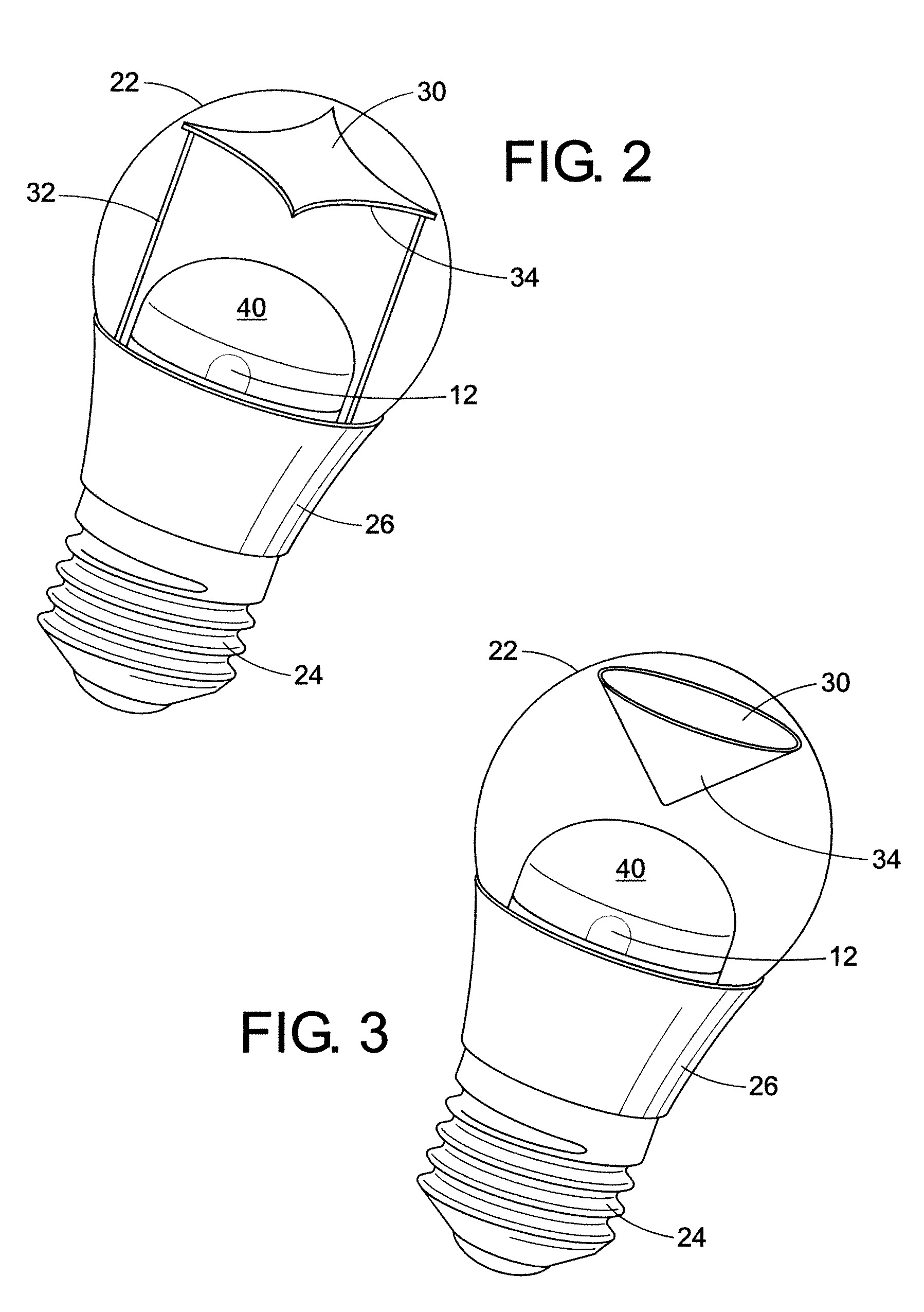
[0010]In accordance with one aspect of the present disclosure, an LED decorative lamp is provided. The LED decorative lamp comprises a light engine having at least one LED mounted on a platform, a current regulated driver configured to provide power to the at least one LED, the driver mounted inside a base, a substantially hollow envelope forming an enclosure over the light engine and driver, and a reflector disposed above the light engine. The reflector being configured to improve the light distribution of the at least one LED.
[0011]In accordance with another aspect of the present disclosure, an LED lamp is provided. The LED lamp comprises one or more LEDs disposed on a platform, a base connector configured to receive a driver and adapted to retrofit into a conventional incandescent light socket, a light transmissive enclosure removably attached to the base and enclosing the one or more LEDs in a substantially hollow space, and a reflector positioned over the one or more LEDs adapted to provide an efficiency of and improve light distribution.
[0012]In accordance with yet another aspect of the present disclosure, a method for improving an LED lamp's efficiency and light distribution is provided. The LED lamp comprises one or more LEDs disposed on a platform and a substantially hollow light transmissive enclosure over the one or more LEDs. The method comprises disposing a reflector over the one or more LEDs within the enclosure, the reflector being coated on at least one surface with a reflective material having a thickness, increasing the thickness to increase the percentage of reflected light, decreasing the thickness to increase the percentage of refracted light, and adjusting the distance of the reflector from the one or more LEDs for adjusting the beam angle.

Problems solved by technology

However, the incandescent filaments are fragile and tend to gradually degrade during a lifetime of a bulb causing the useful light output generated by the filaments to decrease over time.
The increasing fragility of the filament with age eventually leads to breakage.
A low-power, solid state LED light could last up to 100,000 hours (eleven years), far outlasting the life of a typical incandescent bulb.
Widespread use of the LED lighting systems has been limited because the consumers are accustomed to seeing and purchasing the traditional incandescent bulb lights.
The PC lens will create a larger beam angle; however, transmission loss is about 15-20%, resulting in a low lumen per watt (lm / W) of the LED decorative lamp system, such as only 35-45 lm / W.

Method used


Image

  • Reflector (optics) used in LED deco lamp
  • Reflector (optics) used in LED deco lamp
  • Reflector (optics) used in LED deco lamp

Examples


Embodiment Construction

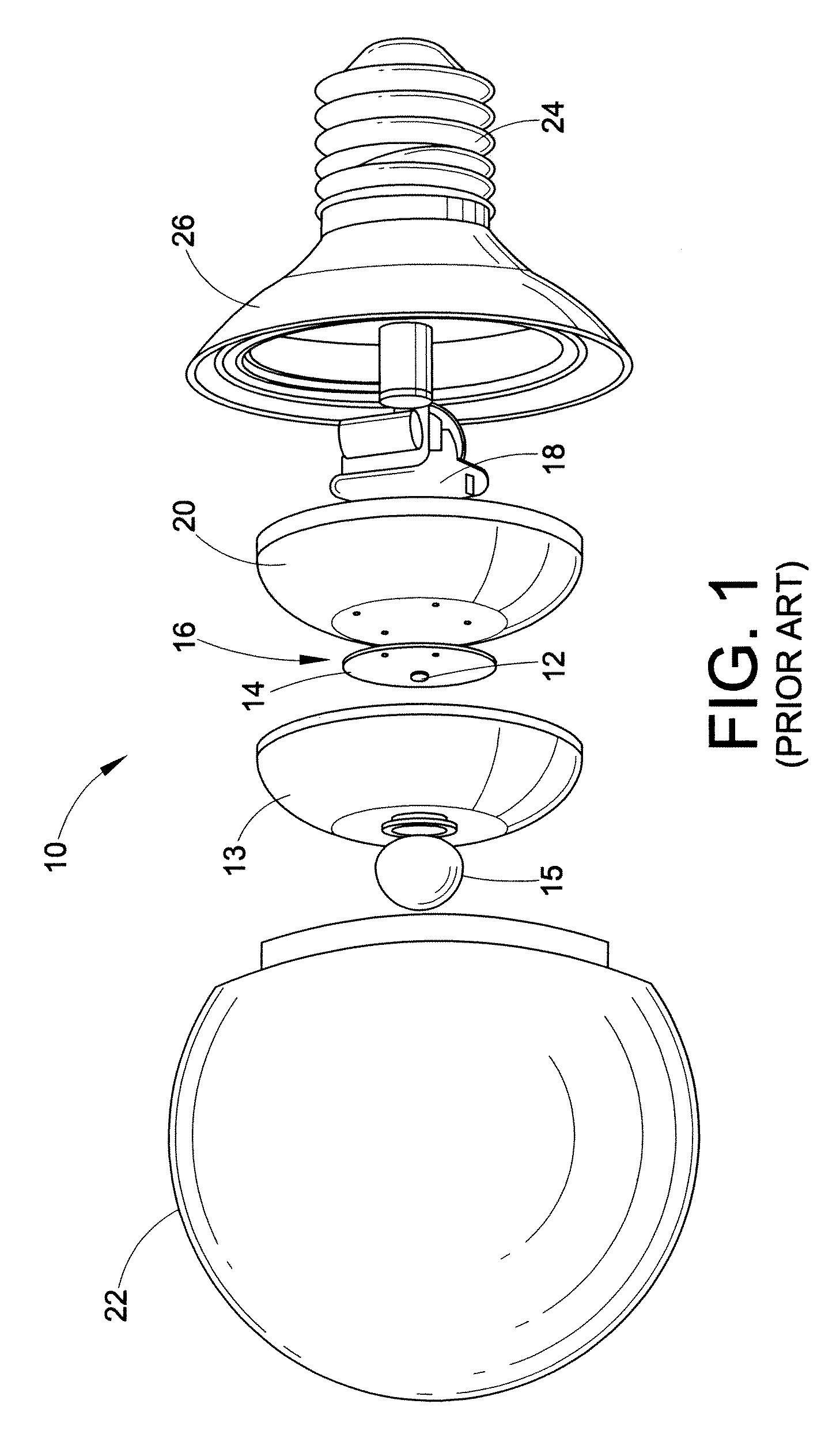
[0017]With reference to FIG. 1, an exploded view of a typical LED decorative lamp 10 is provided that includes one or more LEDs 12 positioned on a platform 14, defining a light engine 16. A driver 18 is provided for powering the LEDs and is a self-contained power supply that is current regulated and may offer dimming by means of pulse width modulation circuits. The LED mounted platform 14 may be positioned directly on the driver 18 or a heat sink 20 may be included between the driver 18 and LED mounted platform 14. The LEDs 12 are one of inorganic and organic light emitting devices which emit light in a spectrum from UV to infrared. Variations in optical performance, viewing angles, and intensity levels are achieved by arranging the LEDs 12 in different patterns. The decorative lamp 10 includes a light cover or enclosure 22. The enclosure 22 may take on any shape desired or necessary for a particular decorative requirement. In the exemplary embodiment illustrated in FIG. 1, the encl...


PUM

PropertyMeasurementUnit
poweraaaaaaaaaa
semi-transparentaaaaaaaaaa
distanceaaaaaaaaaa

Abstract

In accordance with one aspect of the present disclosure, an LED decorative lamp is provided. The LED decorative lamp comprises a light engine having at least one LED mounted on a platform, a current regulated driver configured to provide power to the at least one LED, the driver mounted inside a base, a substantially hollow envelope forming an enclosure over the light engine and driver, and a reflector disposed above the light engine. The reflector is configured to improve the light distribution of the at least one LED.

Description

CROSS REFERENCE TO RELATED APPLICATIONS[0001]This application claims the priority benefit of PCT / CN2010 / 002225, filed Dec. 31, 2010, which is expressly incorporated herein by reference, in its entirety.BACKGROUND[0002]The following relates generally to illumination arts, lighting arts, solid state lighting arts, and related arts, and find particular application in conjunction with the use of reflectors in LED decorative lamps. However, it is to be appreciated that the present exemplary embodiments are amenable to other like applications.[0003]Incandescent light bulbs are widely used in household and commercial lighting, for portable lighting, such as table lamps, car headlamps, and flashlights, and for decorative and advertising lighting. Incandescent lamps are generally omni-directional light sources capable of providing substantially uniform intensity distribution over a wide angle in the far field (greater than 1 meter away from the lamp) and find diverse applications such as in ...

Claims


Application Information

Patent Timeline
Patent Type & Authority Patents(United States)
IPC IPC(8): F21V7/04F21V3/00F21V7/22H01R33/22F21K99/00F21V7/00F21V13/12F21W121/00F21Y101/02
CPCF21V3/00F21K9/135F21K9/50F21V7/0066F21V7/041F21V7/04F21V7/22F21V13/12F21W2121/00F21Y2101/02F21K9/232F21K9/60F21Y2115/10F21V7/28
Inventor GAO, HONGLEI
Owner GE LIGHTING SOLUTIONS LLC
Learn More