Cavity insert film flow cooling

a technology of cavity insert and cooling conduit, which is applied in the field of injection molding system, can solve the problems of defective molded articles and negative impact on the overall molding cycle tim

Inactive Publication Date: 2015-04-14
MOLD MASTERS 2007
View PDF20 Cites 13 Cited by
  • Summary
  • Abstract
  • Description
  • Claims
  • Application Information

AI Technical Summary

Problems solved by technology

That being said, inadequate or inefficient cooling of the outside of the preform can result in defective molded articles, and / or have a negative impact upon the time of the overall molding cycle.

Method used


Image

  • Cavity insert film flow cooling
  • Cavity insert film flow cooling
  • Cavity insert film flow cooling

Examples


Embodiment Construction

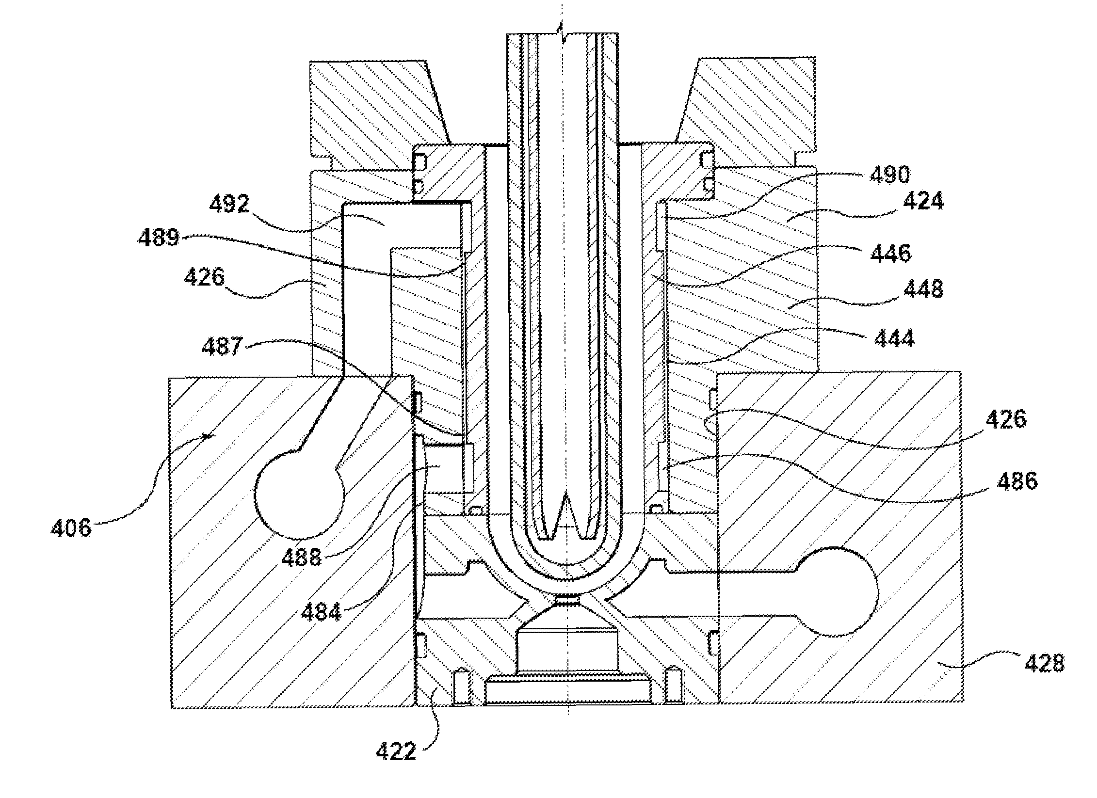
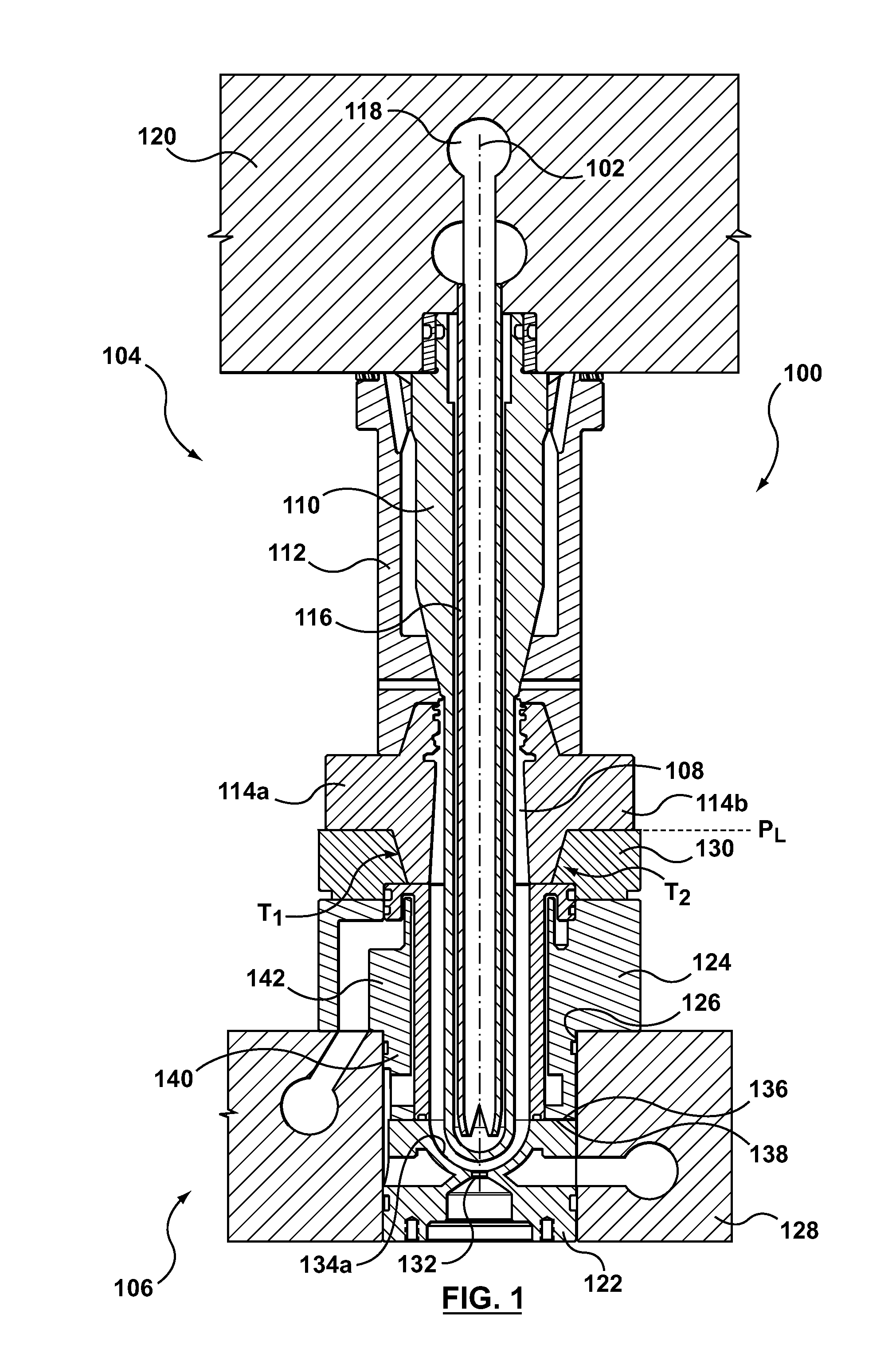
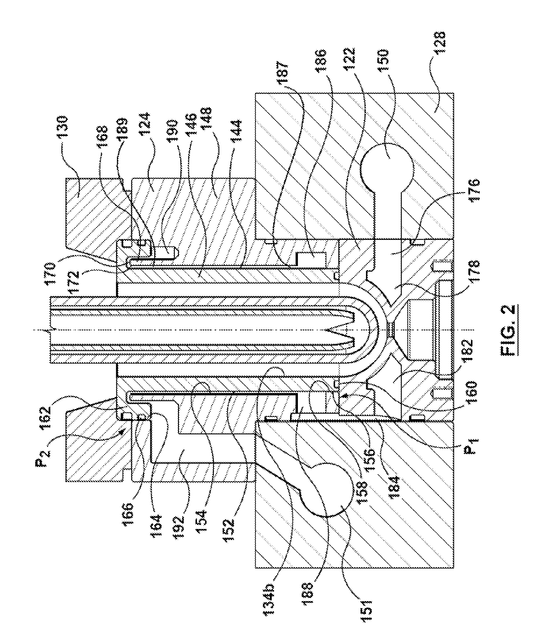
[0020]Specific embodiments of the present invention will now be described with reference to the figures, wherein like reference numbers indicate identical or functionally similar elements. The following detailed description is merely exemplary in nature and is not intended to limit the invention or the application and uses of the invention. A person skilled in the relevant art will recognize that other configurations and arrangements can be used without departing from the scope of the invention. In the following description, “downstream” is used with reference to the direction of mold material flow from an injection unit to a mold cavity of an injection molding system, and also to the order of components or features thereof through which the mold material flows from an injection unit to a mold cavity, whereas “upstream” is used with reference to the opposite direction. Although the description of the embodiments hereof is in the context of hot runner injection molding systems, the i...


PUM

PropertyMeasurementUnit
lengthaaaaaaaaaa
outer diameteraaaaaaaaaa
inner diameteraaaaaaaaaa

Abstract

A cavity insert for a mold stack is disclosed, the cavity insert being dimensioned to define a continuous annular cavity insert cooling chamber. The cavity insert also provides a first and second decompression chamber in fluid communication with each end of the cavity insert cooling chamber. Also disclosed is a chamber extension feature in fluid communication with the cavity insert cooling chamber to promote cooling in the downstream region of the cavity insert.

Description

FIELD OF THE INVENTION[0001]The invention relates generally to injection molding systems and in particular to cooling conduit configurations in a preform mold stack.BACKGROUND OF THE INVENTION[0002]In the art of injection molding, a typical injection mold will contain one or more mold cores and cavities that correspond to the shape of the molded article being produced. A melt stream of moldable material is injected from an injection molding machine into the mold cavities through a hot runner system, where it is allowed to solidify for a period of time before the mold is opened and the newly molded parts are ejected.[0003]One of the most significant factors in affecting the overall cycle time required to produce one or a plurality of molded articles is the time required to solidify or cool the newly molded articles within the mold cavity before the parts are ejected.[0004]In injection molding applications such as the molding of polyethylene terephthalate (PET) preforms, the ability t...

Claims


Application Information

Patent Timeline
Patent Type & Authority Patents(United States)
IPC IPC(8): B29C45/73B29C45/26B29C45/72B29K105/00
CPCB29C45/7312B29K2105/253B29K2105/258B29B11/08B29C2949/07B29C33/02
Inventor LAUSENHAMMER, MANFRED
Owner MOLD MASTERS 2007
Why Eureka
Try Eureka