Cooling arrangement for a turbine component

a cooling arrangement and turbine technology, applied in the direction of machines/engines, liquid fuel engines, lighting and heating apparatus, etc., can solve the problem of reducing the uniformity of cooling

Inactive Publication Date: 2012-02-09
SIEMENS ENERGY INC
View PDF10 Cites 59 Cited by
  • Summary
  • Abstract
  • Description
  • Claims
  • Application Information

AI Technical Summary

Problems solved by technology

However, the impinged air then flows across the wall surface, interfering with other impingement jets.
However, the coolant becomes warmer with distance, reducing uniformity of cooling.

Method used


Image

  • Cooling arrangement for a turbine component
  • Cooling arrangement for a turbine component
  • Cooling arrangement for a turbine component

Examples


Embodiment Construction

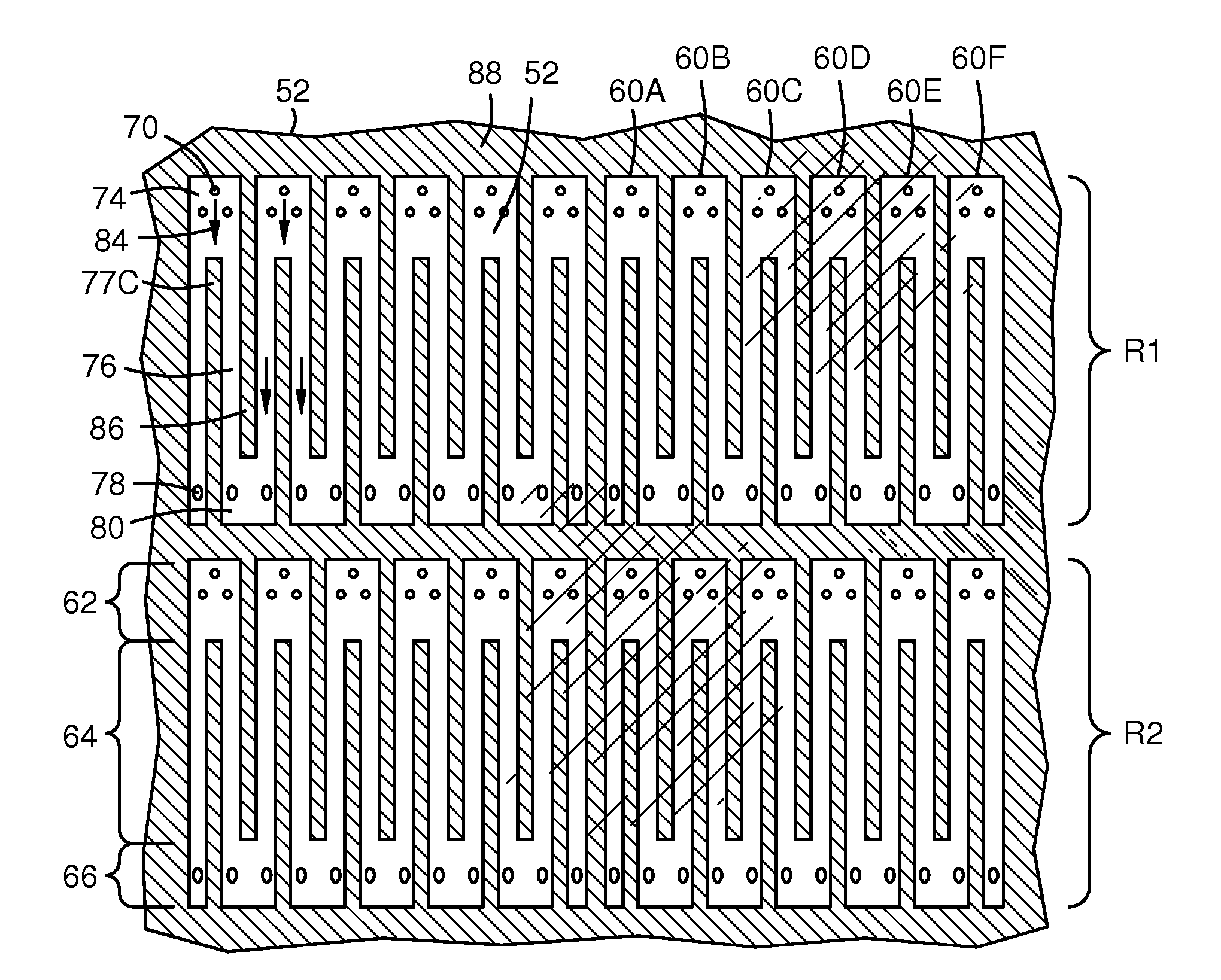
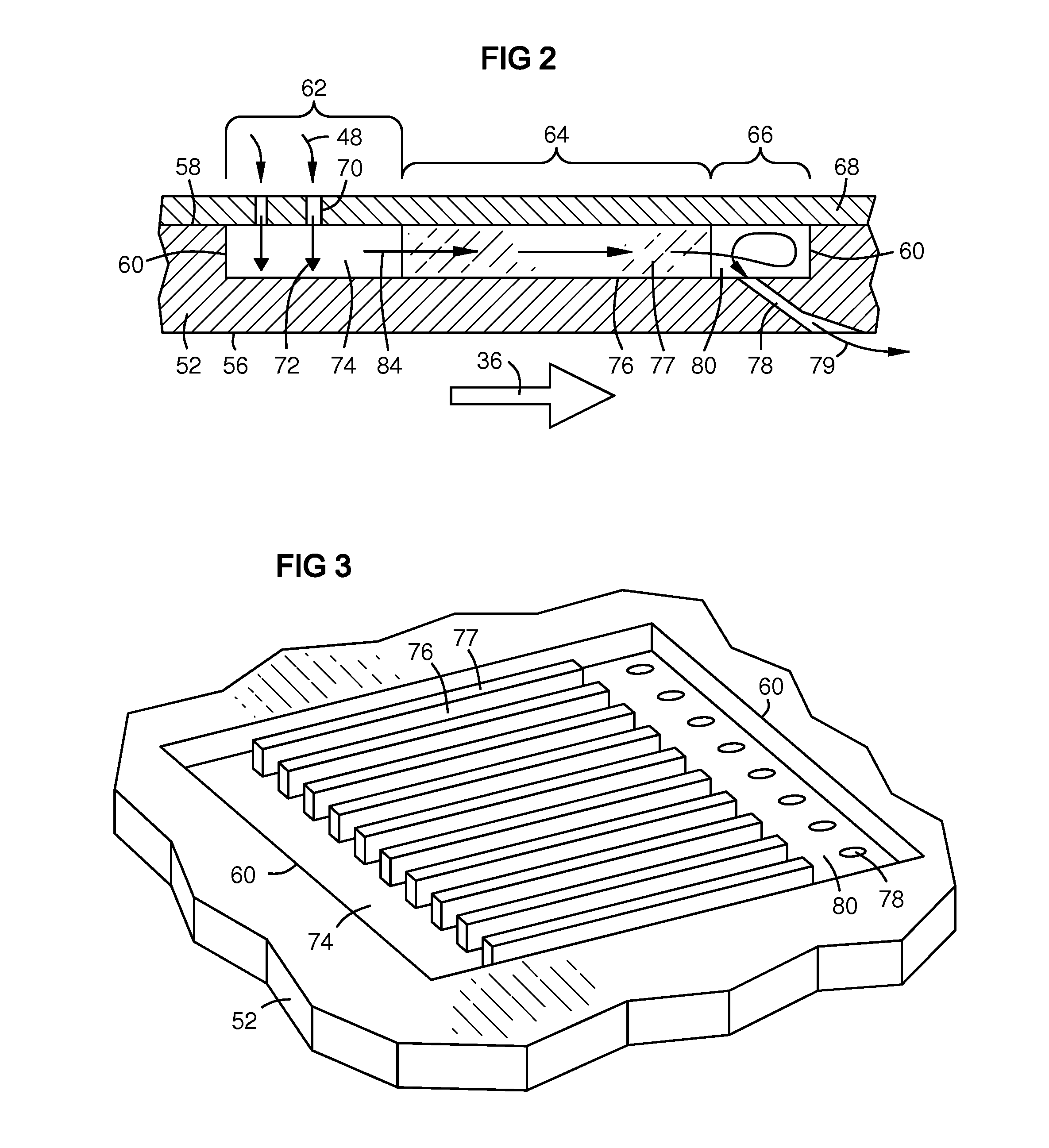
[0014]In one embodiment, the present invention combines an impingement cooling zone chamber, a convective heat transfer zone with multiple channels, and a film cooling zone chamber leading to plurality of metering film cooling outlets, in a way that provides more flexible independent optimization of each zone and a higher degree of synergy and complementation among the zones that maximizes cooling efficiency and uniformity.

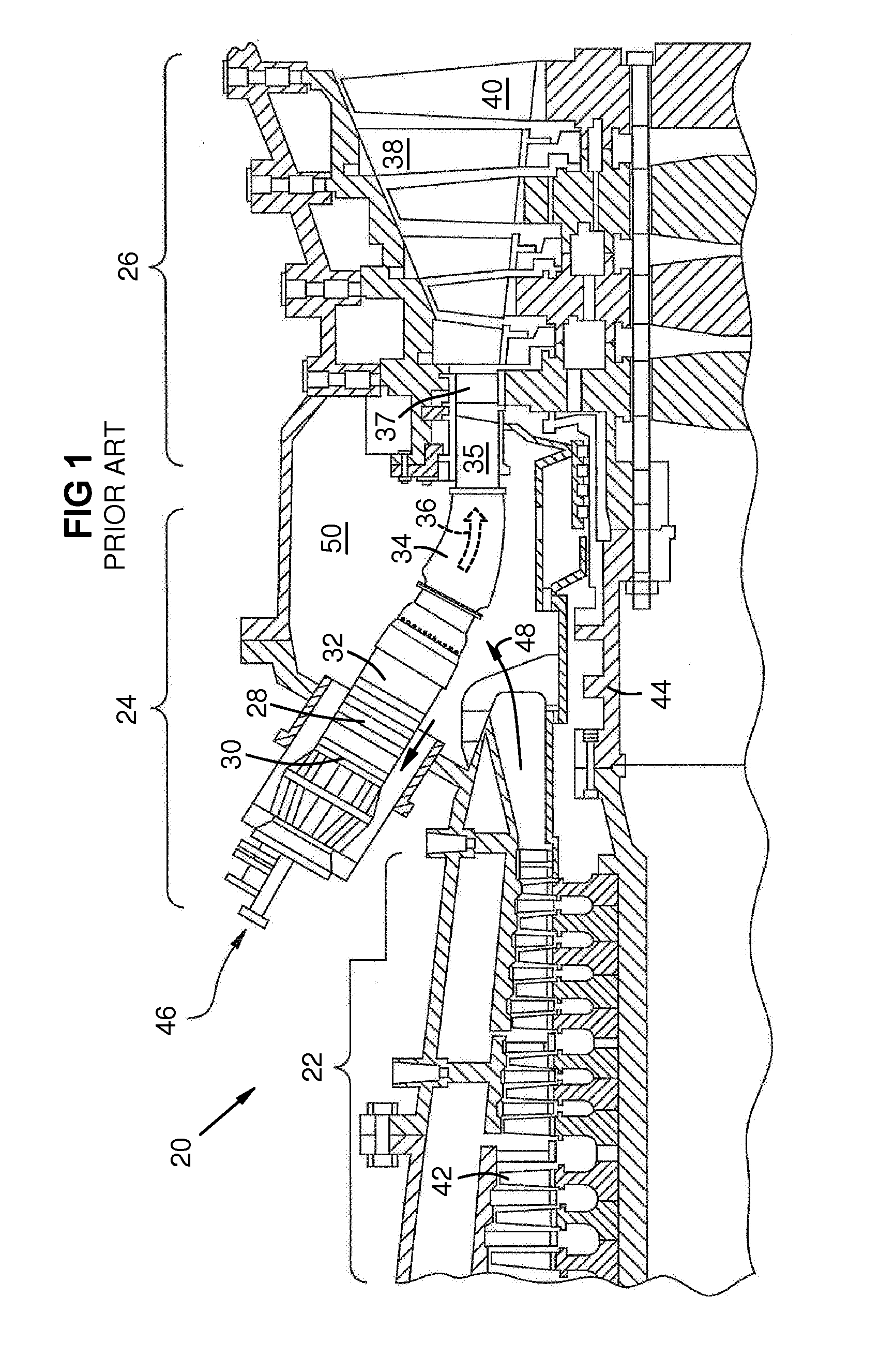
[0015]FIG. 1 is a partial side sectional view of a gas turbine engine 20 with a compressor section 22, a combustion section 24, and a turbine section 26 as known in the art. Each combustor 28 has an upstream end 30 and a downstream end 32. A transition duct 34 and an intermediate exit piece 35 transfer the combustion gas 36 from the combustor to the first row of airfoils 37 of the turbine section 26. The first row of airfoils 37 may be stationary vanes 38 or rotating blades 40, depending on the turbine design. Compressor blades 42 are driven by the turbine blades ...


PUM


Abstract

A cooled component wall (52) with a combustion gas (36) on one side (56) and a coolant gas (48) with higher pressure on the other side (58). The wall includes a cooling chamber (60) with an impingement cooling zone (62), a convective cooling zone (64), and a film cooling zone (66). Impingement holes (70) admit and direct jets (72) of coolant against the wall, thence the coolant passes among heat transfer elements such as channels (76) and fins (78) to the film cooling zone (66) where it passes through holes in the wall that direct a film of the coolant along the combustion side of the wall. The chamber may be oriented with the impingement zone (62) downstream and the film cooling zone (66) upstream, relative to the combustion gas flow (36). This provides two passes of the coolant (84, 79) in opposite directions over the respective opposite sides of the wall (56, 58).

Description

FIELD OF THE INVENTION[0001]This invention relates to cooling of turbine component walls using a cooling fluid, such as on a gas turbine duct.BACKGROUND OF THE INVENTION[0002]Components such as combustor-to-turbine transition ducts that are in combustion gas flow areas of gas turbines require cooling to maintain design temperatures. Cooling efficiency is important in order to minimize the usage of air diverted from the compressor for cooling. Impingement cooling is a technique in which a perforated wall is spaced from a hot wall to be cooled. Cooling air flows through the perforations and forms jets that impinge on the hot wall. However, the impinged air then flows across the wall surface, interfering with other impingement jets. This is called “cross-flow interference” herein. Other cooling techniques use elements such as cooling channels, fins, and pins to provide increased surface area for convective / conductive heat transfer. However, the coolant becomes warmer with distance, red...

Claims


Application Information

Patent Timeline
Patent Type & Authority Applications(United States)
IPC IPC(8): F01D25/08
CPCF01D9/023F23R3/005F23R2900/03042F23R2900/03043F23R2900/03045F05D2260/201F05D2260/202F05D2260/22141F23R2900/03044F05D2260/204
Inventor HSU, JOHANMORRISON, JAY A.
Owner SIEMENS ENERGY INC
Why Eureka
Try Eureka