Continuous contact X-ray source

a technology of x-ray source and continuous contact, which is applied in the direction of x-ray tubes, traction harnesses, fastening devices, etc., can solve the problems of significant power expenditure, difficult to achieve outside of the laboratory environment, and difficult to achieve significant power expenditur

Active Publication Date: 2015-04-14
TRIBO LABS
View PDF17 Cites 3 Cited by
  • Summary
  • Abstract
  • Description
  • Claims
  • Application Information

AI Technical Summary

Benefits of technology

[0007]These and other aspects of the invention are more fully comprehended upon review of this disclosure.

Problems solved by technology

Acceleration of the electrons to generate a useful quantity of x-rays, however, generally requires expenditure of significant power, particularly when considering the small percentage of such electrons which actually result in x-ray emissions.
However, utilization of such methods to provide a sufficient intensity of x-rays to be commercially useful, and doing so outside of a laboratory environment, may be difficult.

Method used


Image

  • Continuous contact X-ray source
  • Continuous contact X-ray source
  • Continuous contact X-ray source

Examples


Embodiment Construction

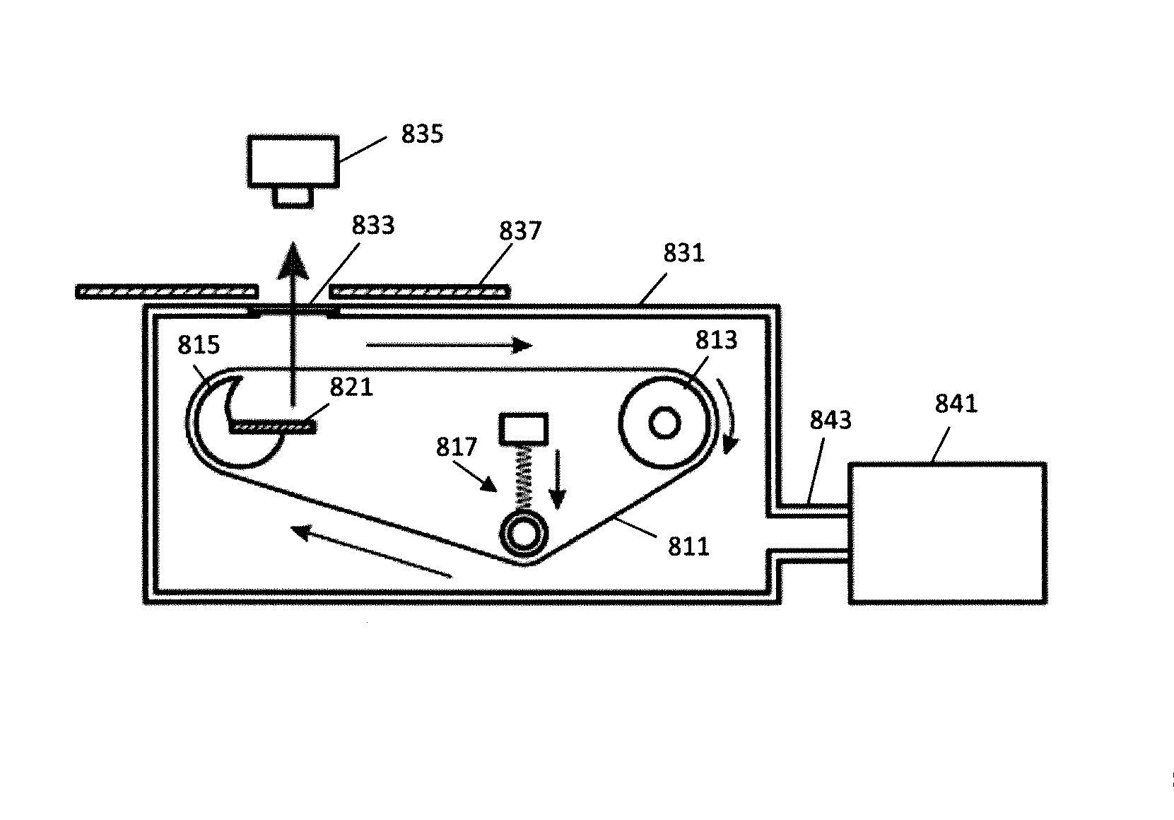
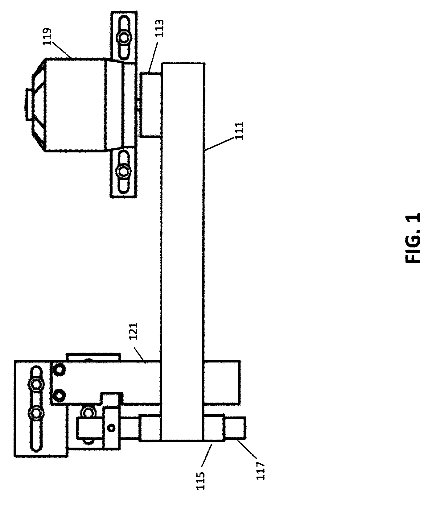
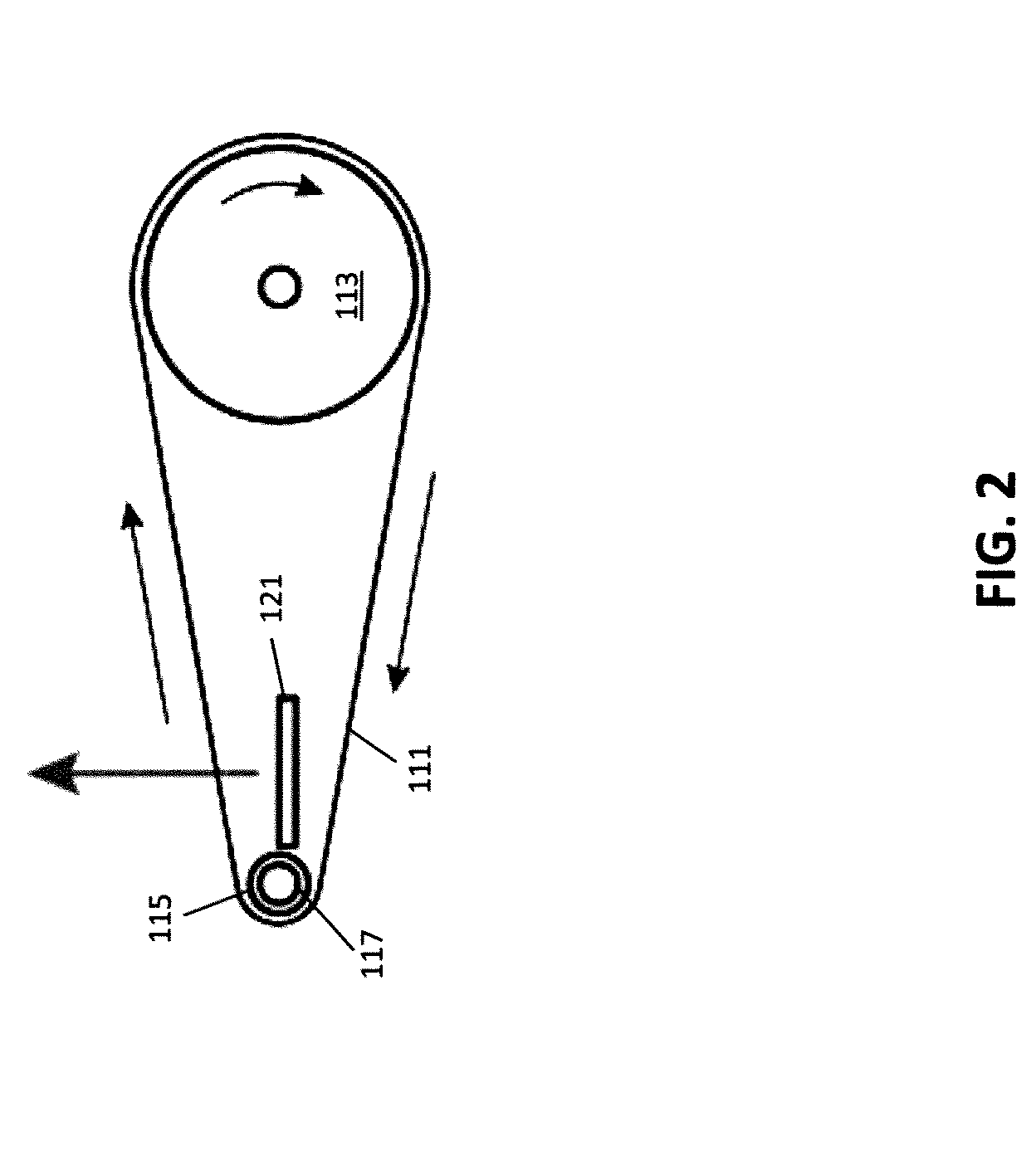
[0037]FIGS. 1-3 show views of representations of portions of a device for x-ray generation in accordance with aspects of the invention. In most embodiments the portions of the device shown in FIGS. 1-3 are enclosed in one or more chambers of a housing configured for maintenance of a low fluid pressure environment. In some embodiments only some portions may be so enclosed. For example, in some embodiments a motor of the device may not be so enclosed, and in some embodiments only portions of a device proximate to (and including) a target shelf may be so enclosed. In such various embodiments, generally the housing is substantially opaque to x-rays, other than a window which is substantially transparent to x-rays.

[0038]The device includes a band 111 looped between a drive roller 113 and a contact material 117. The band may be a continuous band, although various embodiments may include bands that are not continuous. In some embodiments the band may be comprised of material that varies wi...


PUM


Abstract

An x-ray device utilizes a band of material to exchange charge through tribocharging within a chamber maintained at low fluid pressure. The charge is utilized to generate x-rays within the housing, which may pass through a window of the housing. Various contact rods may be used as part of the tribocharging process.

Description

BACKGROUND OF THE INVENTION[0001]The present invention relates generally to generation of high-energy radiation, and more particularly to generation of high energy radiation by mechanical motion.[0002]X-rays are used in a variety of ways. X-rays may be used for medical or other imaging applications, crystallography related applications including material analysis, or in other applications.[0003]X-rays are generally generated by electron braking (bremmstrahlung) or inner shell electron emission within a material. Historically, other than through natural phenomena, x-rays generally have been generated by accelerating electrons into a material, such as a metal, with a small proportion of the electrons causing x-rays through bremmstrahlung or knocking electrons present in the material out of inner orbitals, for example K-shell orbitals, with x-rays being generated as electrons in higher energy orbitals transition to the lower energy orbitals. Acceleration of the electrons to generate a ...

Claims


Application Information

Patent Timeline
Patent Type & Authority Patents(United States)
IPC IPC(8): H01J35/02
CPCH01J35/02H01J35/065H05G2/00H01J35/112H01J35/20H01J35/186
Inventor CAMARA, CARLOS G.VALENTINE, MARK G.GAMLIELI, ZACHARY J.LUCAS, BENJAMIN A.KAMKAR, DAVID M.CORTES, JR., PEDROM, VASHISH NARAYANJIMENEZ, GILBERTOCUADRA, DANIEL E.
Owner TRIBO LABS
Why Eureka
Try Eureka