
Multilayer X-ray source target with high thermal conductivity

a multi-layer, thermal conductivity technology, applied in the direction of x-ray tube targets, x-ray tube laminated targets, x-ray tube targets and convertors, etc., can solve the problems of reducing the overall thermal conductivity of the target, and reducing the overall thermal conductivity.

Active Publication Date: 2015-04-14
GENERAL ELECTRIC CO
View PDF47 Cites 34 Cited by
  • Summary
  • Abstract
  • Description
  • Claims
  • Application Information

AI Technical Summary

Problems solved by technology

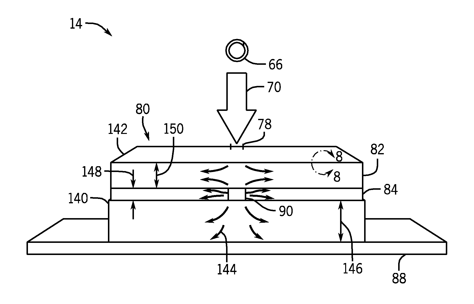
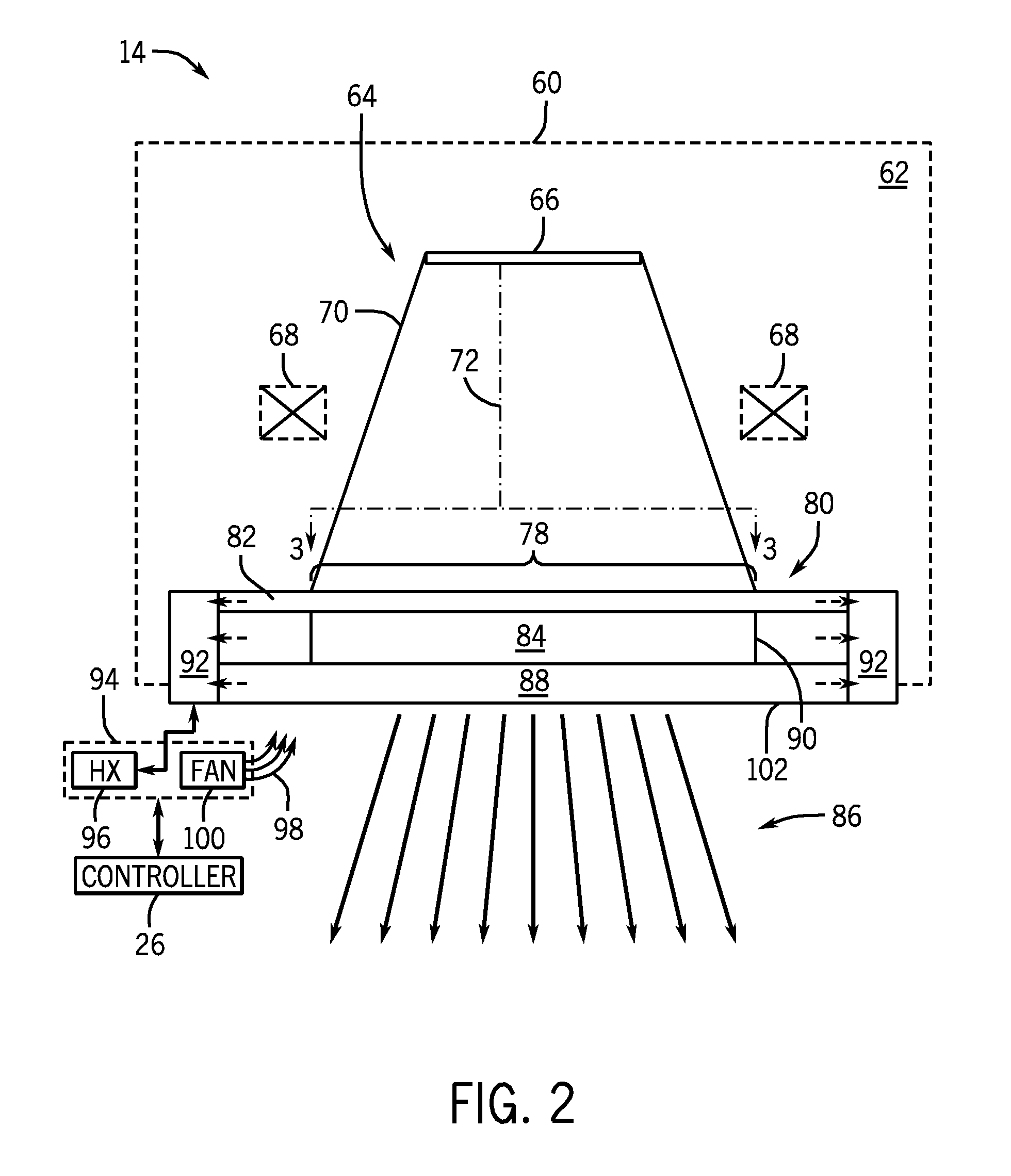
For example, as noted above, during the operation of an X-ray source, the electron beam impacts and deposits energy into the source target, resulting in heat and X-ray radiation.
However, the relatively large amount of heat produced during operation, if not mitigated, can damage the X-ray source (e.g., melt the target).
However, when rotation is the means of avoiding overheating, the amount of deposited heat is limited by the rotation speed (RPM) and the life of the supporting bearings, this limits the amount of deposited heat and X-ray flux.
This also increases the overall volume, and weight of the X-ray source systems.
When the target is actively cooled, such cooling generally occurs far from the electron beam impact area, which in turn significantly limits the electron beam power that can be applied to the target.
In both situations, the restricted heat removal ability of the cooling methods markedly lowers the overall flux of X-rays that are generated by the X-ray tube.

Method used


Image

  • Multilayer X-ray source target with high thermal conductivity
  • Multilayer X-ray source target with high thermal conductivity
  • Multilayer X-ray source target with high thermal conductivity

Examples


Embodiment Construction

[0024]One or more specific embodiments will be described below. In an effort to provide a concise description of these embodiments, all features of an actual implementation may not be described in the specification. It should be appreciated that in the development of any such actual implementation, as in any engineering or design project, numerous implementation-specific decisions must be made to achieve the developers' specific goals, such as compliance with system-related and business-related constraints, which may vary from one implementation to another. Moreover, it should be appreciated that such a development effort might be complex and time consuming, but would nevertheless be a routine undertaking of design, fabrication, and manufacture for those of ordinary skill having the benefit of this disclosure.

[0025]When introducing elements of various embodiments of the present invention, the articles “a,”“an,”“the,” and “said” are intended to mean that there are one or more of the ...


PUM


Abstract

In one embodiment, an X-ray source is provided that includes one or more electron emitters configured to emit one or more electron beams and one or more source targets configured to receive the one or more electron beams emitted by the one or more electron emitters and, as a result of receiving the one or more electron beams, to emit X-rays. Each source target of the X-ray source includes a first layer having one or more first materials; and a second layer in thermal communication with the first layer and having one or more second materials. The first layer is positioned closer to the one or more emitters than the second layer, the first material has a higher overall thermal conductivity than the second layer, and the second layer produces the majority of the X-rays emitted by the source target.

Description

BACKGROUND[0001]This section is intended to introduce the reader to various aspects of art that may be related to various aspects of the present disclosure, which are described and / or claimed below. This discussion is believed to be helpful in providing the reader with background information to facilitate a better understanding of the various aspects of the present disclosure. Accordingly, it should be understood that these statements are to be read in this light, and not as admissions of prior art.[0002]A variety of diagnostic, laboratory, and other systems (e.g., radiation-based treatment systems) may utilize X-ray tubes as a source of radiation. Typically, the X-ray tube includes a cathode and an anode. An emitter within the cathode may emit a stream of electrons. The anode may include a target that is impacted by the stream of electrons. As a result of this impact, the target may emit radiation. A large portion of the energy deposited into the target by the electron beam produce...

Claims


Application Information

Patent Timeline
Patent Type & Authority Patents(United States)
IPC IPC(8): H01J35/06B82Y99/00H01J5/18G21K1/06H01J35/12
CPCG21K1/06H01J35/12H01J5/18H01J2235/088H01J2235/087H01J2235/086H01J35/116H01J35/13
Inventor LEE, SUSANNE MADELINEBAHADUR, RAJMANDAL, SUDEEP
Owner GENERAL ELECTRIC CO
Learn More