Method and apparatus for detecting internal rail defects

a technology for internal rails and defects, applied in the direction of instruments, measurement devices, and analysis of solids using sonic/ultrasonic/infrasonic waves. it can solve the problem of normal difficulty or inability to detect defects

Active Publication Date: 2015-04-21
NORDCO WISCONSIN
View PDF22 Cites 13 Cited by
  • Summary
  • Abstract
  • Description
  • Claims
  • Application Information

AI Technical Summary

Problems solved by technology

Such defects are normally difficult or impossible to detect with ultrasonic beams directed perpendicular to the surface of the rail.

Method used


Image

  • Method and apparatus for detecting internal rail defects
  • Method and apparatus for detecting internal rail defects
  • Method and apparatus for detecting internal rail defects

Examples


Embodiment Construction

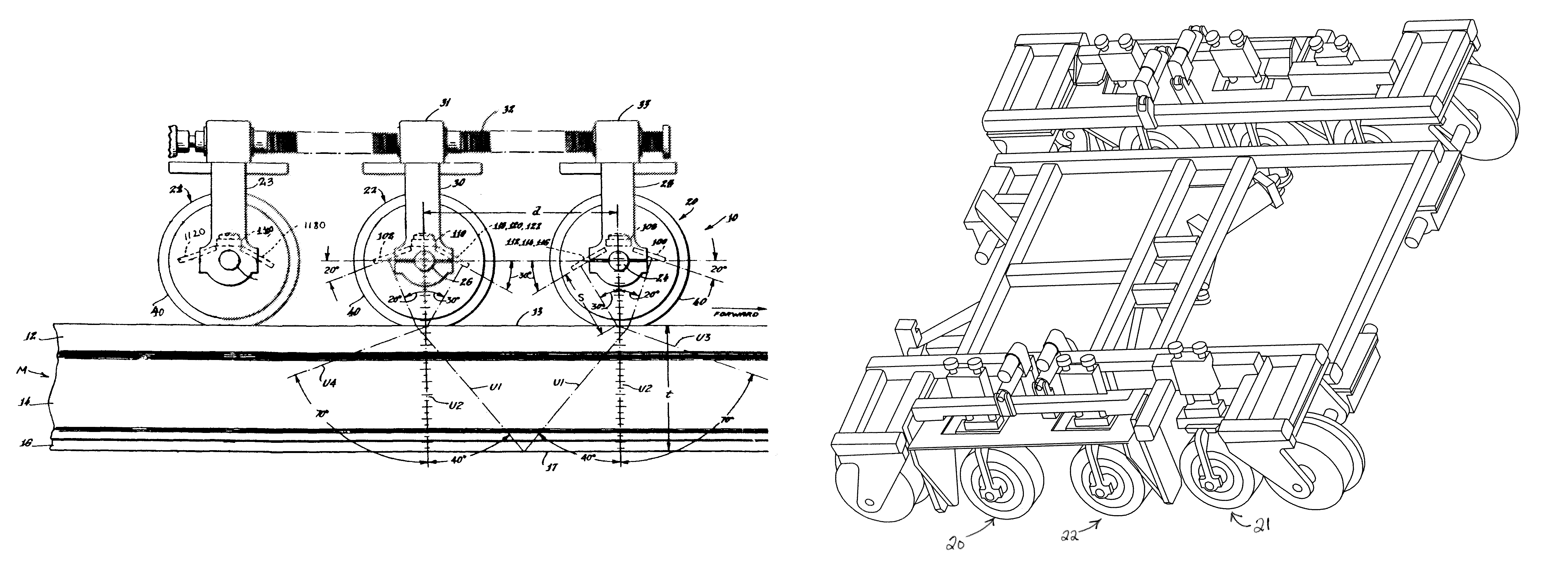
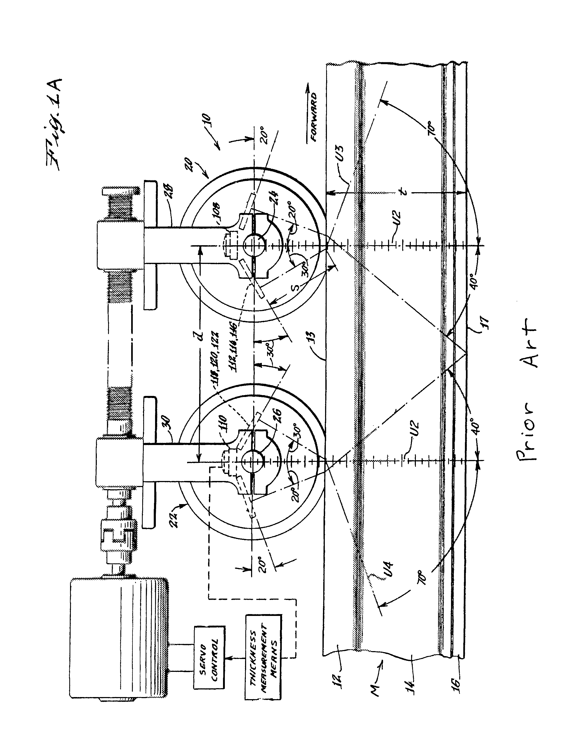
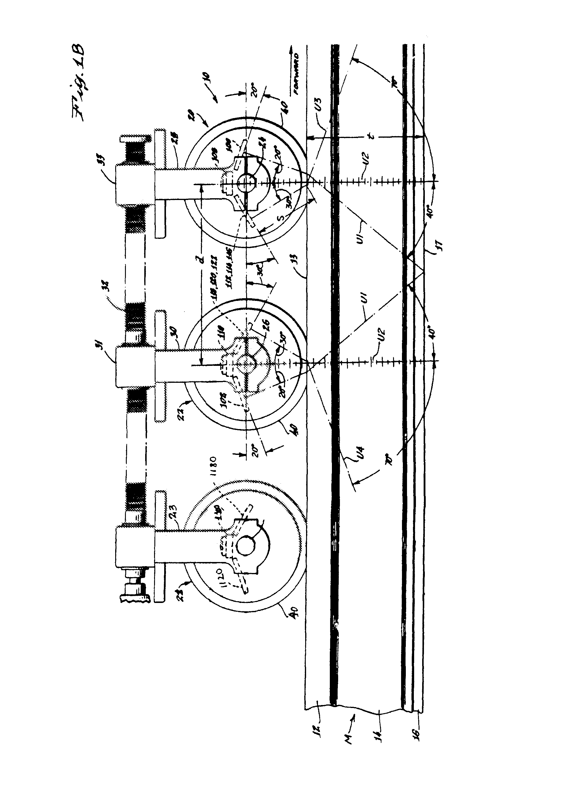
[0022]FIG. 1 illustrates a prior art two wheel ultrasonic inspection system 10 described in U.S. Pat. No. 4,165,648, which is arranged to detect flaws and defects in a length of test material M, illustrated as a rail having a substantially rectangular head 12 with an upper surface 13, a vertical web 14, and a base 16 with a bottom surface 17 typically resting on ties (not shown.)

[0023]Arranged for rolling contact along the upper surface 13 of rail head 12 are a leading test wheel 20 and a trailing test wheel 22. The wheels 20 and 22 rotate about fixed shafts 24 and 26 secured respectively to support arms 28 and 30 which are spring loaded downward by conventional means upon a carriage (not shown) which propels the wheels along the length of test material M.

[0024]As illustrated in FIG. 1 the leading and trailing wheels 20 and 22 have zero degree transducers 108 and 110 which are oriented to emit beams U2 of ultrasonic energy downward perpendicularly through Teflon (polyetrafluoroethyl...


PUM

PropertyMeasurementUnit
angleaaaaaaaaaa
angleaaaaaaaaaa
angleaaaaaaaaaa

Abstract

An ultrasonic rail inspection system designed to detect defects in a rail which result from longitudinal cracks that propagate in the horizontal and transverse plane of the rail. Detection of this type of defect is possible by directing an ultrasonic beam into the rail at a predetermined angle from the perpendicular to the surface of the rail. The predetermined angle must be sufficient to detect these normally undetectable defects and can be in the range of 8° to 14° from the perpendicular.

Description

CROSS-REFERENCE TO RELATED APPLICATIONS[0001]This application is a continuation in part of U.S. patent application Ser. No. 12 / 108,401 filed Apr. 23, 2008, in the name of Dominick A. Pagano, and entitled Method And Apparatus For Detecting Internal Rail Defects. U.S. patent application Ser. No. 12 / 108,401 is hereby incorporated by reference in its entirety. This application also incorporates by reference U.S. Pat. No. 4,165,648 issued to inventor Dominick A. Pagano.FIELD OF INVENTION[0002]This invention relates to a method and apparatus for the ultrasonic inspection of a test material and more particularly to the ultrasonic inspection of a railroad rail which may contain detail fractures caused by metal fatigue.BACKGROUND OF THE INVENTION[0003]The Federal Railroad Administration (FRA) reported, as of Dec. 1, 2006, that between 1995 and 2005 a total of 276 derailments occurred on the four Class I U.S. railroads and that these derailments were caused by broken rails. One of these derai...

Claims


Application Information

Patent Timeline
Patent Type & Authority Patents(United States)
IPC IPC(8): G01N29/04G01N29/22G01N29/24G01N29/265
CPCG01N29/04G01N29/225G01N29/265G01N29/043G01N29/221G01N29/2493G01N2291/2623G01N2291/056
Inventor PAGANO, DOMINICK A.
Owner NORDCO WISCONSIN
Why Eureka
Try Eureka