
Intelligent monitoring system for beam end expansion device of long-span railway steel bridge

A telescopic device and intelligent monitoring technology, which is applied in the direction of measuring device, general control system, control/adjustment system, etc., can solve the problems of failure to give reasonable countermeasures, lack of monitoring system for telescopic devices, and inaccurate spatial displacement characteristics of railway steel bridge end areas. Clear and other issues

Pending Publication Date: 2019-01-18
RAILWAY ENG RES INST CHINA ACADEMY OF RAILWAY SCI +2
View PDF4 Cites 9 Cited by
  • Summary
  • Abstract
  • Description
  • Claims
  • Application Information

AI Technical Summary

Problems solved by technology

[0006] (1) The health monitoring system of the long-span railway steel bridge does not incorporate the monitoring of the telescopic device at the beam end into its system function, and the telescopic device also lacks an independent monitoring system, resulting in inconsistent spatial displacement characteristics of the railway steel bridge end area. It is clear that the daily diseases of the telescopic device cannot be prevented in advance, and reasonable countermeasures cannot be given after the disease occurs, and the public maintenance department cannot obtain targeted technical advice in time and make reasonable decisions, so that the telescopic device cannot be maintained effectively and in a timely manner repair
[0007] (2) Existing patents mostly focus on the monitoring and evaluation methods of road modular large-displacement expansion joints, and railway-related monitoring patent technologies are only aimed at a single state parameter of a simple top-loading beam end expansion device, such as only involving scissors Monitoring of fork deformation, resulting in incomplete monitoring and insufficient evaluation

Method used


Image

  • Intelligent monitoring system for beam end expansion device of long-span railway steel bridge
  • Intelligent monitoring system for beam end expansion device of long-span railway steel bridge
  • Intelligent monitoring system for beam end expansion device of long-span railway steel bridge

Examples


Embodiment Construction

[0036] In order to make the object, technical solution and advantages of the present invention clearer, the present invention will be further described in detail below in conjunction with the accompanying drawings and embodiments. It should be understood that the specific embodiments described here are only used to explain the present invention, not to limit the present invention.

[0037] An intelligent monitoring system for the expansion device at the end of a long-span railway steel bridge, such as Figure 7 shown, including:

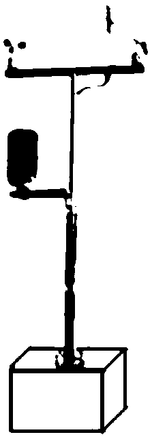
[0038] Environmental impact variable monitoring sub-modules, such as figure 2 As shown, it is integrated with a temperature and humidity meter and a wind direction anemometer, and is fixed on the pier abutment of the bridge side by expansion bolts or fixed on the pier abutment guardrail by a special fixture;

[0039] The main approach bridge end displacement monitoring sub-module is used to monitor the longitudinal displacement of the main approac...


PUM


Abstract

The invention relates to an intelligent monitoring system for a beam end expansion device of a long-span railway steel bridge. The intelligent monitoring system comprises an environmental impact variable monitoring sub-module, a main guide bridge beam end displacement monitoring sub-module, an expansion device main body monitoring sub-module, a beam end running condition monitoring sub-module anda rail inspection vehicle beam end detection sub-module. Through adoption of the intelligent monitoring system, intelligent monitoring of the beam end expansion device is realized, and monitoring content covers environmental impact variables; main lead bridge end displacement monitoring is realized; longitudinal and lateral displacement monitoring of the expansion device, vertical deflection and strain monitoring, and video monitoring are realized; beam end driving state monitoring is realized; and access to rail inspection vehicle detection data is realized. The intelligent monitoring systemrealizes automatic real-time monitoring and evaluation of the working state of the beam end expansion device, has the functions of intelligent monitoring, data analysis and evaluation, and state prediction and diagnosis, covers the monitoring of various static and dynamic parameters of environments and structures as well as driving state, and provides technical reference for the engineering department.

Description

technical field [0001] The invention relates to an intelligent monitoring system of an expansion device at the end of a long-span railway steel bridge. Background technique [0002] Under the coupling effects of train live load, temperature, wind, etc., there are complex spatial displacements at the ends of long-span railway steel bridges. In order to adapt to this displacement and ensure the safety and stability of the high-speed train passing through the beam end, it is often necessary to install a large displacement telescopic device and a rail telescopic adjuster at the beam end. The beam end telescopic devices commonly used in long-span railway steel bridges in my country are divided into two types: bottom-supported and top-supported. The two types of telescopic devices are different in terms of structure and working principle. The under-supported beam end telescopic device provides vertical support for the sleeper by placing the supporting beam below. The supporting b...

Claims


Application Information

Patent Timeline
Patent Type & Authority Applications(China)
IPC IPC(8): G01D21/02G05B19/042
CPCG05B19/0428G01D21/02G05B2219/2612
Inventor 刘晓光郭辉赵欣欣李旭伟柴雪松暴学志凌烈鹏许兆军肖鑫苏朋飞
Owner RAILWAY ENG RES INST CHINA ACADEMY OF RAILWAY SCI
Learn More