
Track detection method and track inspection trolley

A track inspection trolley and track inspection technology, which is applied to railway inspection vehicles, railway car body parts, railway vehicle shape measuring devices, etc., can solve problems such as single working mode, low work efficiency, and inability to meet work needs

Active Publication Date: 2018-12-25
GUANGZHOU GEOELECTRON
View PDF7 Cites 9 Cited by
  • Summary
  • Abstract
  • Description
  • Claims
  • Application Information

AI Technical Summary

Problems solved by technology

However, in practice, it is found that the trolley-type track detector and the track geometric state measuring instrument have a single working mode, which cannot meet the work requirements in different application scenarios. Moreover, the trolley-type track gauge uses a gyroscope to measure the smooth parameters of the track. Its measurement accuracy depends on the accuracy of the inertial sensor, which is difficult to meet the accuracy requirements in the industry; while the measuring instrument uses a total station to measure the absolute position of the track, the accuracy is relatively high, but the work efficiency is very low

Method used


Image

  • Track detection method and track inspection trolley
  • Track detection method and track inspection trolley
  • Track detection method and track inspection trolley

Examples


Embodiment 1

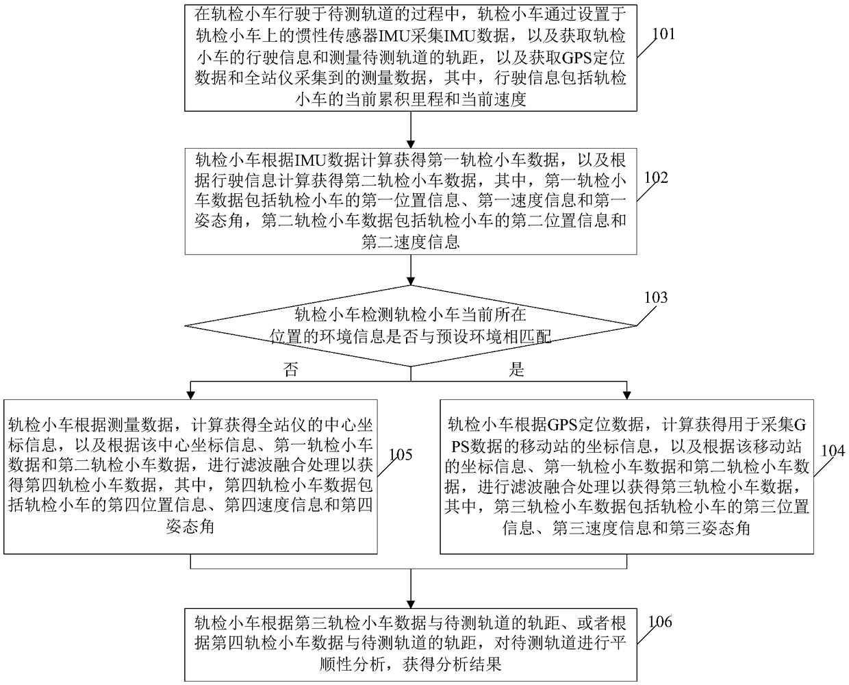
[0069] see figure 1 , figure 1 It is a schematic flowchart of a track detection method disclosed in an embodiment of the present invention. Such as figure 1 As shown, the track detection method may include the following steps.

[0070] 101. When the track inspection trolley is running on the track to be tested, the track inspection trolley collects IMU data through the inertial sensor IMU installed on the track inspection trolley, obtains the driving information of the track inspection trolley and measures the gauge of the track to be tested, And obtain GPS positioning data and measurement data collected by the total station, wherein the driving information includes the current accumulated mileage and current speed of the track inspection trolley.

[0071] It should be noted that before step 101 is executed, the track inspection car can use the 1PPS second pulse of GPS to synchronize the time of the inertial sensor IMU and the total station, so that the time of the GPS, ine...

Embodiment 2

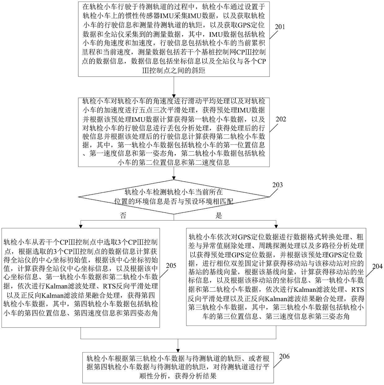
[0092] see figure 2 , figure 2 It is a schematic flowchart of another track detection method disclosed in the embodiment of the present invention. Such as figure 2 As shown, the track detection method may include the following steps.

[0093] 201. When the track inspection trolley is running on the track to be tested, the track inspection trolley collects IMU data through the inertial sensor IMU installed on the track inspection trolley, and obtains the driving information of the track inspection trolley and measures the gauge of the track to be tested. And obtain the GPS positioning data and the measurement data collected by the total station. Among them, the IMU data includes the angular velocity and acceleration of the track inspection car, the driving information includes the current accumulated mileage and current speed of the track inspection car, and the measurement data includes several foundation piles. The data information of CPⅢ control points on the network, ...

Embodiment 3

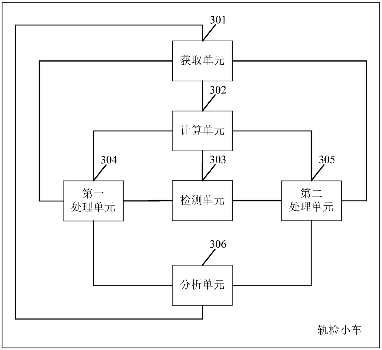
[0141] see image 3 , image 3 It is a structural schematic diagram of a track inspection trolley disclosed in the embodiment of the present invention. Such as image 3 As shown, the track inspection trolley can include:

[0142] The acquisition unit 301 is used to collect IMU data through the inertial sensor IMU provided on the track inspection trolley during the process of the track inspection trolley running on the track to be tested, and to obtain the driving information of the track inspection trolley and measure the gauge of the track to be tested , and obtain GPS positioning data and measurement data collected by the total station, wherein the driving information includes the current accumulated mileage and current speed of the track inspection trolley;

[0143] The calculation unit 302 is used to calculate and obtain the first track inspection trolley data according to the IMU data acquired by the acquisition unit 301, and calculate and obtain the second track inspe...


PUM


Abstract

The embodiment of the invention discloses a track detection method and a track inspection trolley. The method comprises the following steps: obtaining IMU data, traveling information on the track inspection trolley, track gauge of a tested track, GPS positioning data and measurement data of a total station; Calculating a first rail inspection trolley data and a second rail inspection trolley data;Detecting the environmental information of the current position of the track inspection trolley; When the surrounding environment indicated by the environmental information matches with the preset environment, calculating the coordinate information of the mobile station and obtaining the data of the third track inspection trolley by combining the data of the first track inspection trolley and thedata of the second track inspection trolley; When there is a mismatch, the center coordinate information of the total station instrument is calculated and the data of the first track inspection trolley and the second track inspection trolley are combined to obtain the data of the fourth track inspection trolley. According to the third track inspection trolley data or the fourth track inspection trolley data, combined with the gauge for ride comfort analysis to obtain the analysis results. By implementing the embodiment of the invention, different working modes can be selected for different application scenes, and the measurement accuracy and the work efficiency can be improved.

Description

technical field [0001] The invention relates to the technical field of track detection, in particular to a track detection method and a track detection trolley. Background technique [0002] Due to the advantages of high-speed rail, such as large carrying capacity, good stability, and high speed, all countries in the world regard the development of high-speed rail as an extremely important part of their national transportation development strategies. Among them, in order to ensure the safety of train operation, there are very high requirements for the smoothness of the track. [0003] At present, in order to detect the smoothness of the track, trolley-type track inspection instruments and track geometric state measuring instruments have been developed one after another. However, in practice, it is found that the trolley-type track detector and the track geometric state measuring instrument have a single working mode, which cannot meet the work requirements in different appl...

Claims


Application Information

Patent Timeline
Patent Type & Authority Applications(China)
IPC IPC(8): B61D15/08B61K9/08
Inventor 高威莫庆禄
Owner GUANGZHOU GEOELECTRON
Learn More