Counterbalanced elevating conveyor

a technology of counterbalanced and elevating conveyors, which is applied in the direction of conveyor parts, mechanical conveyors, transportation and packaging, etc., can solve the problems of inconvenience, fall or hoist, and possible obstacles for workers, and achieve the effect of simple and convenient operation and safety benefits

Inactive Publication Date: 2015-04-21
SKARLUPKA MFG
View PDF12 Cites 0 Cited by
  • Summary
  • Abstract
  • Description
  • Claims
  • Application Information

AI Technical Summary

Benefits of technology

[0007]It is an object of the present invention to provide an elevating conveyor which is simpler and more easily operated and which provides safety benefits.

Problems solved by technology

The chain fall or hoist represents an additional cost an inconvenience and a possible obstacle to workers.

Method used


Image

  • Counterbalanced elevating conveyor
  • Counterbalanced elevating conveyor
  • Counterbalanced elevating conveyor

Examples


Embodiment Construction

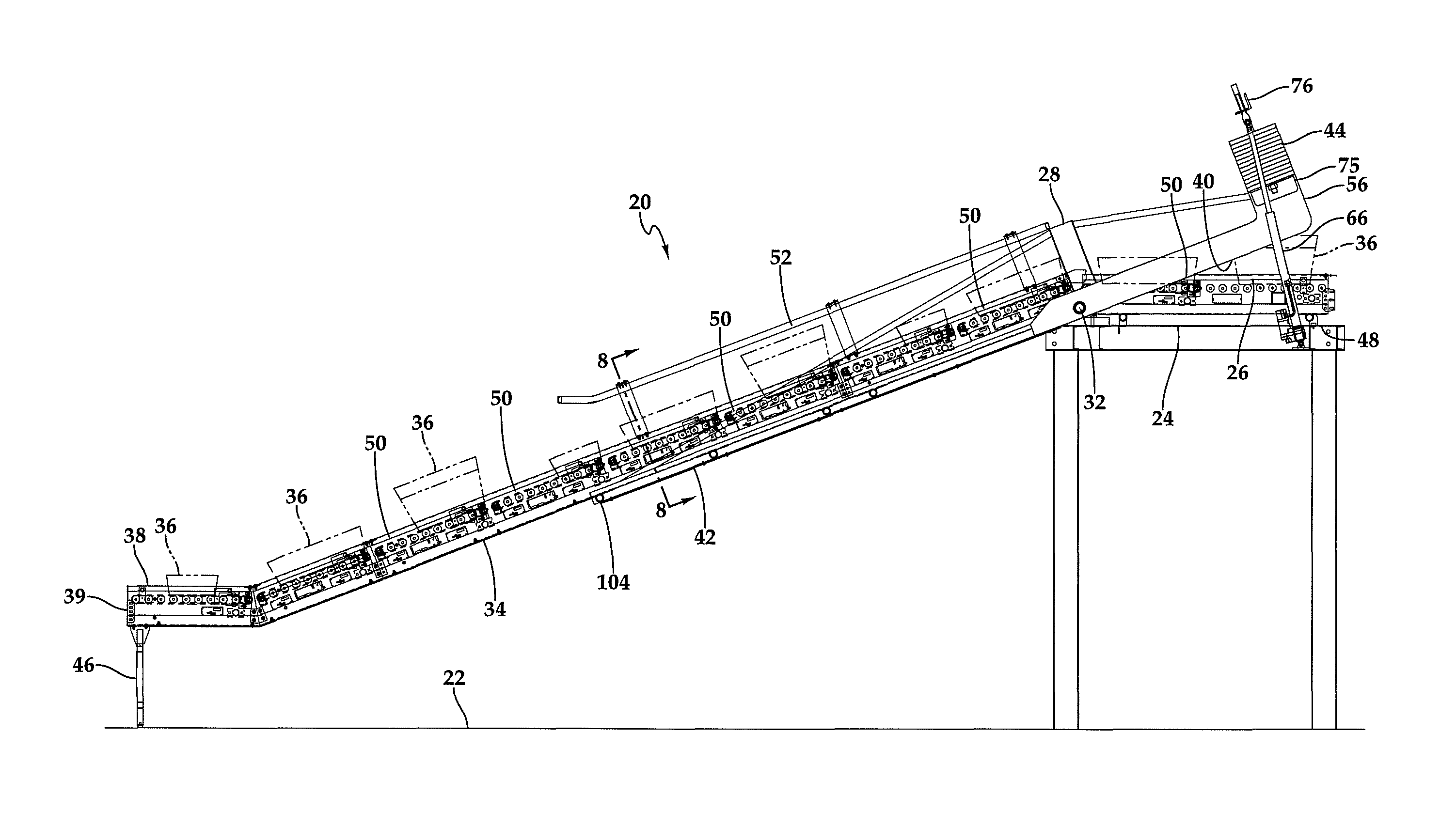
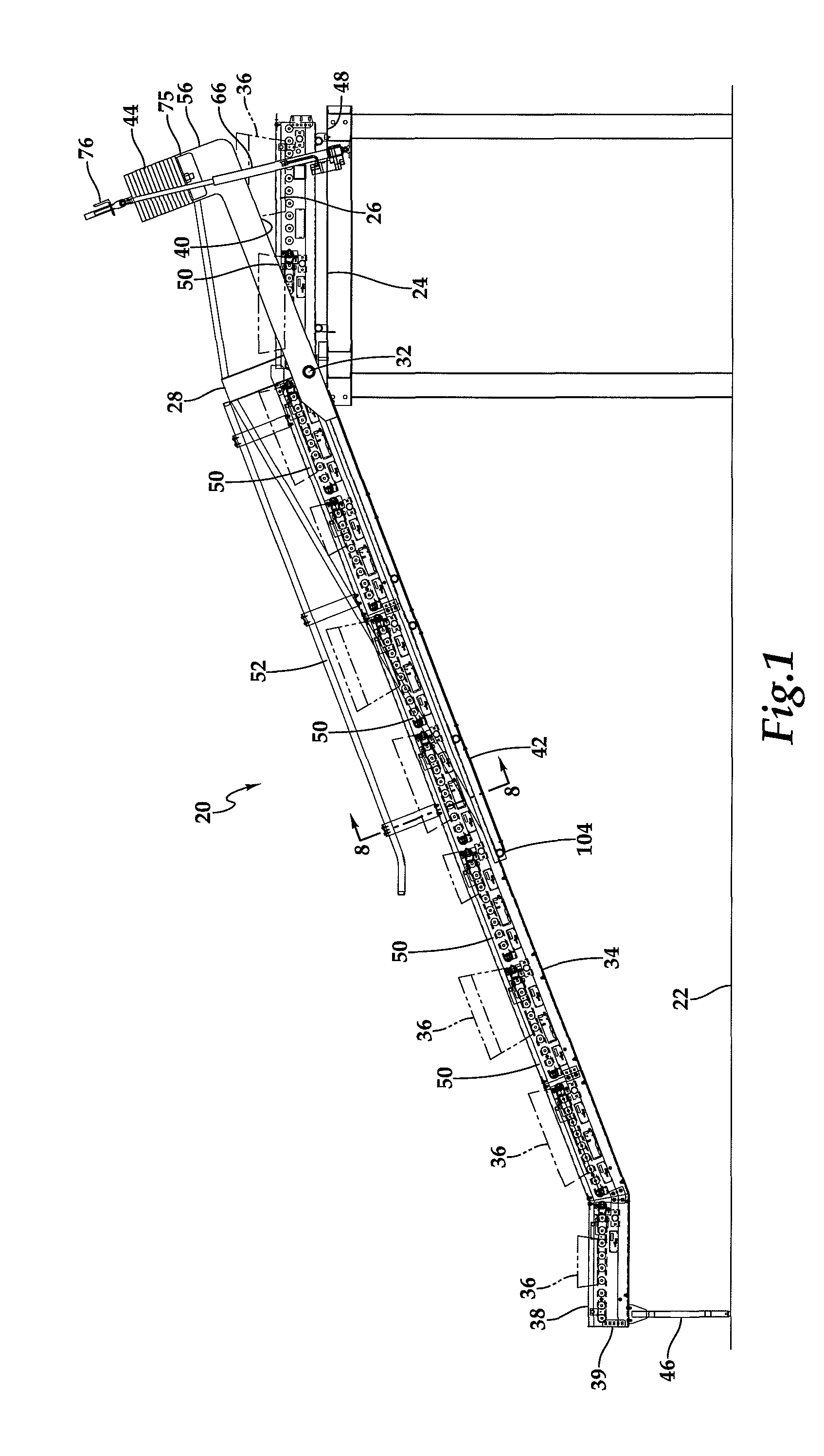
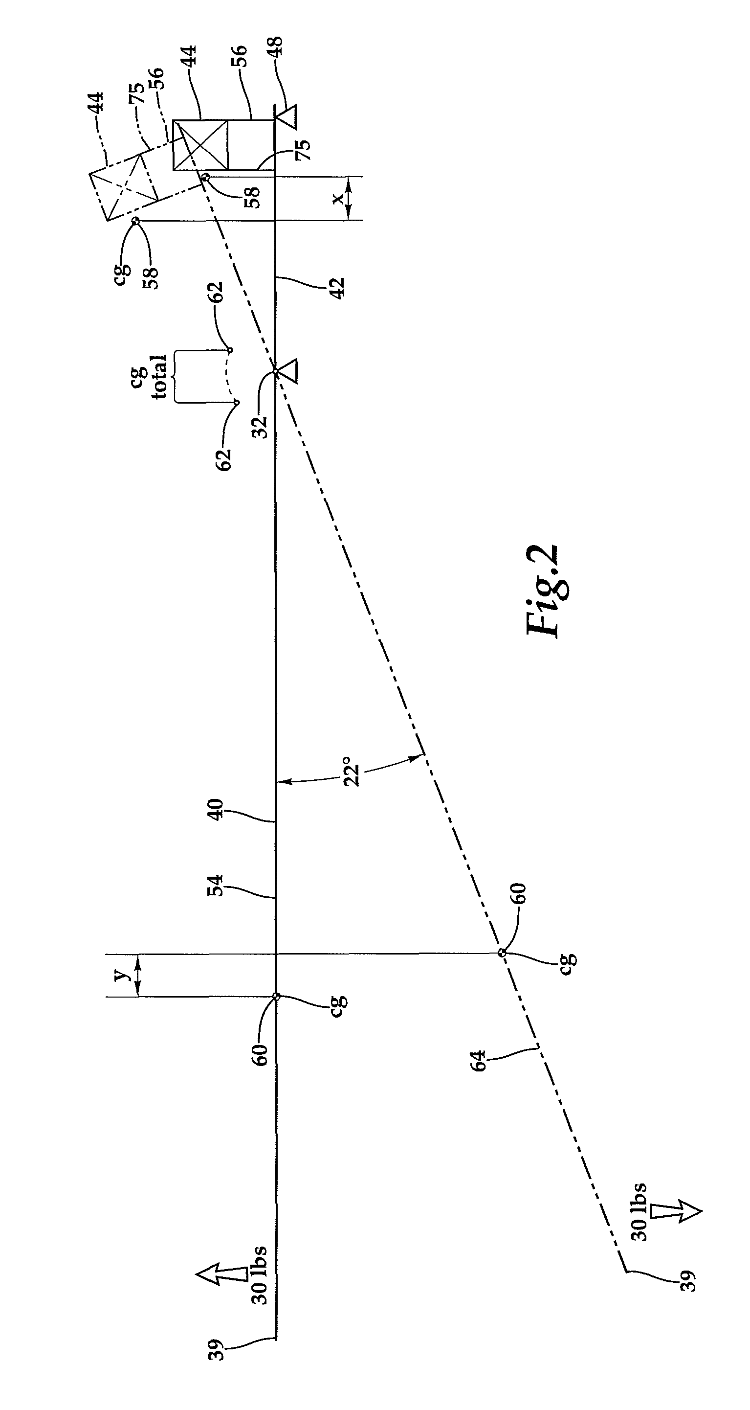
[0019]Referring more particularly to FIGS. 1-9 wherein like numbers refer to similar parts, a conveyor system 20 is shown in FIG. 1. The conveyor system 20 is mounted to extend between a loading floor 22 and an upper platform or distribution level 24. The conveyor system 20 comprises a bridge structure 28 and an elevating conveyor mounted to the bridge structure. The bridge structure is itself mounted to a pivot shaft 32 on the upper platform 24 so the bridge can pivot about a horizontal axis to pass through a vertical plane 30 which extends through the pivot shaft. The elevating conveyor 34 is arranged to transport packages or cartons 36 from a loading section 38 at a lower end 39 of the elevating conveyor to an elevated conveyor 26. The bridge 28 supports the elevating conveyor 34 when the bridge and the elevating conveyor are in the down position as illustrated in FIG. 1. The bridge 28 has a first portion 42 which supports a counterweight 44 and a second portion 40 which supports...


PUM


Abstract

An elevating conveyor is mounted to a pivoting bridge so that the elevating conveyor can be shifted by a 22 degree rotation between a lowered position in engagement with a loading floor and an elevated storage position where the conveyor is out of the way of the loading floor. A counterweight arrangement is mounted to the bridge to bias the conveyor toward the loading floor when it is in a lowered position, and to bias it toward the elevated storage position when it is in the up position. The conveyor may be readily moved between the positions with a moderate application of force. The force may be applied by an operator standing on the loading floor or by a liner actuator mounted between the bridge and a fixed structure.

Description

CROSS REFERENCES TO RELATED APPLICATIONS[0001]Not applicable.STATEMENT AS TO RIGHTS TO INVENTIONS MADE UNDER FEDERALLY SPONSORED RESEARCH AND DEVELOPMENT[0002]Not applicable.BACKGROUND OF THE INVENTION[0003]The present invention relates to conveyors in general and to in particular to elevating conveyors which can be retracted for storage.[0004]Conveyor systems have been developed for both speedy and efficient loading or unloading of packages or containers from or to transportation vehicles or storage areas. The packages and or containers are typically not sorted or only partially sorted when they arrive and are loaded unloaded in the most convenient sequence, normally starting with those most accessible, and fed onto an elevating conveyor which delivers the packages or containers to a sorting conveyor above the working floor which distributes individual packages or containers to workstations on the working floor below, where the packages or the containers' contents may be further so...

Claims


Application Information

Patent Timeline
Patent Type & Authority Patents(United States)
IPC IPC(8): B65G41/00B65G47/56B65G21/12
CPCB65G21/12
Inventor SKARLUPKA, DONALD BRUCE
Owner SKARLUPKA MFG
Why Eureka
Try Eureka