Peripheral environment detection system and device

a detection system and peripheral environment technology, applied in the field of forms of technology, can solve the problems of less use, less accurate detection of rear movement, and less effective rear movement detection field of vision of the mounted handlebars of cyclists, and achieve the effects of less complex adjustment and use, simple design and material, and light weigh

Pending Publication Date: 2016-12-15
SHAFOVALOFF THOMAS EDWARD
View PDF5 Cites 2 Cited by
  • Summary
  • Abstract
  • Description
  • Claims
  • Application Information

AI Technical Summary

Benefits of technology

[0010]It is the object of this invention to provide rearward visual information and threat detection in a device with fewer parts, that is lighter in weight and less complex to adjust and use. This is done by using simple design and material in a way that reduces the need for user adjustment input and the opportunity for breakage of numerous complex parts. Additionally,

Problems solved by technology

Other devices, like those that may be mounted on a cyclists handlebars are not in the most effective field of vision for rear movement detection and are typically made of more costly materials making acquisition and therefore use less likely.
Those mirrored devices

Method used


Image

  • Peripheral environment detection system and device
  • Peripheral environment detection system and device
  • Peripheral environment detection system and device

Examples


Embodiment Construction

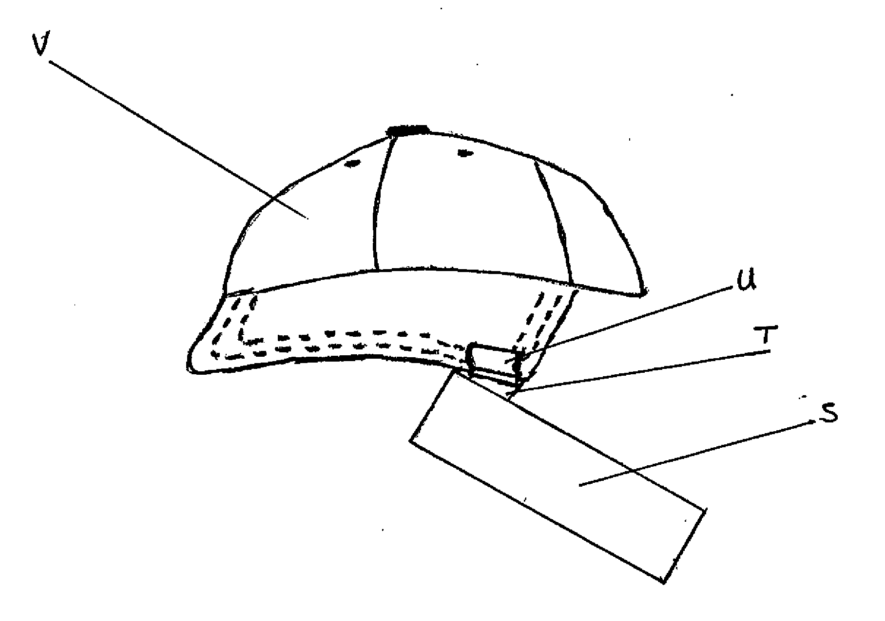
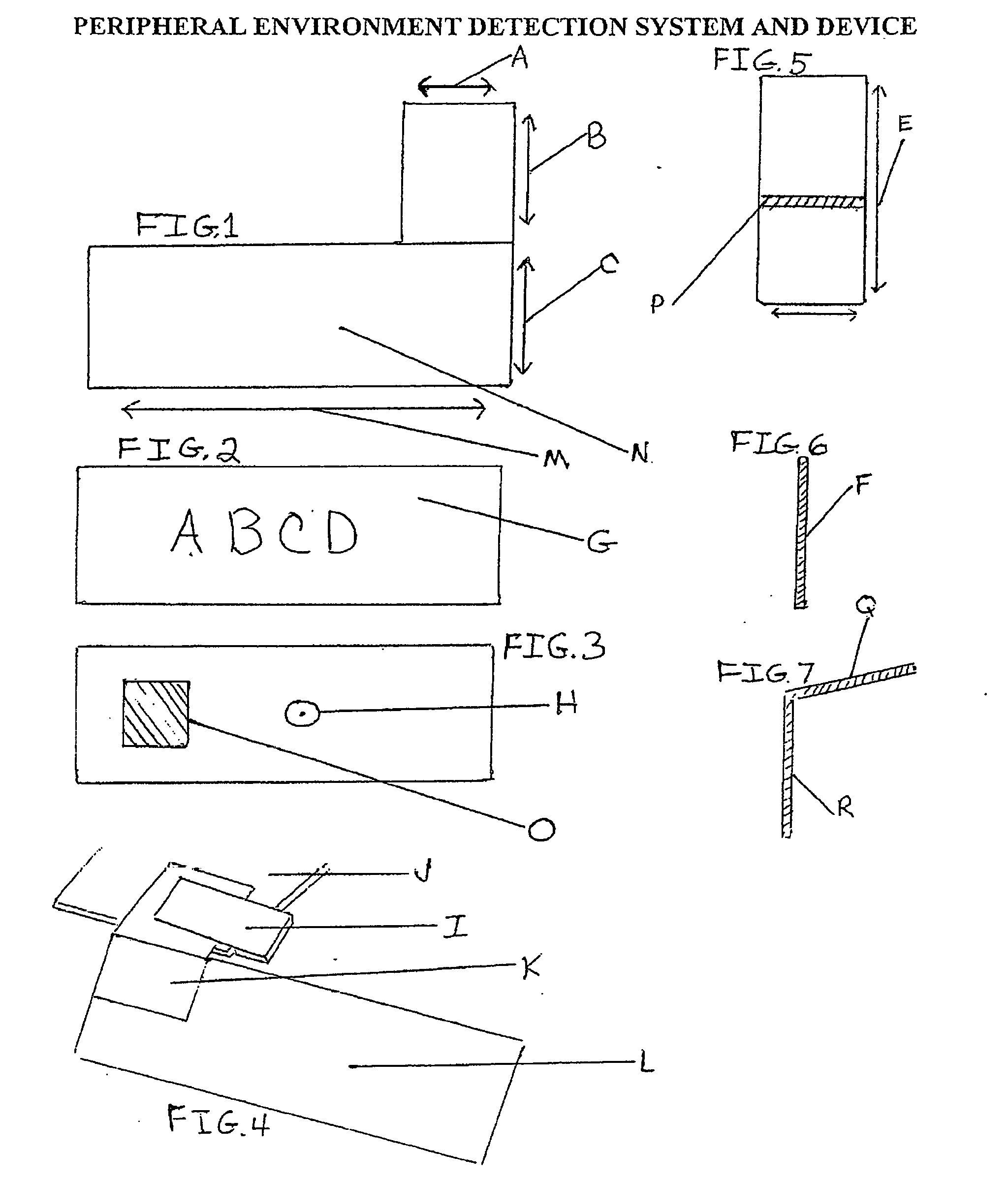
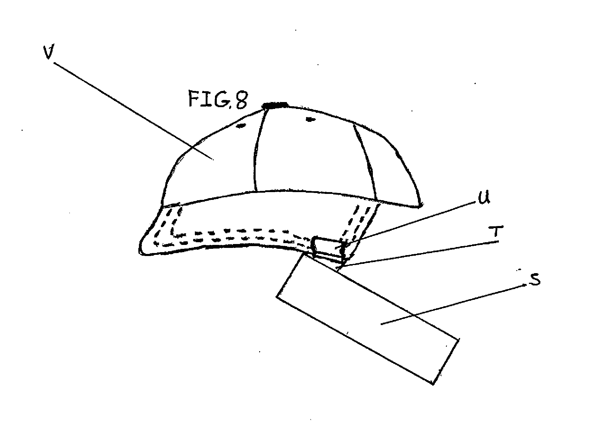
[0022]The following detailed description makes reference to the drawings which have previously been briefly identified that include embodiments of the invention beyond its simplest form. The construction of this invention in its simplest form is by use of planar, flat, mirrored plastic material of sufficient property to allow bending a tab into a retained position from the planar plastic piece folded toward the mirrored rear side of the device not quite perpendicular to the mirror plane without fracturing the material. When cut to form one piece the tab is bent to mount on head gear such as a ball cap using various methods including clips and adhesive. See Drawing—FIG. 1. The tab can be separate. See FIGS. 4 and 5. The tab can be made on the right side of the mirror material, FIG. 1, FIG. 4 and FIG. 8, for an embodiment mounted on the front left side of head gear like a ball cap brim and, or, the opposite, right side for an embodiment mounted on the right side of a ball cap brim. Th...


PUM


Abstract

This peripheral environment detection system and device accomplishes improvement of an individuals awareness of his surroundings not in line of sight, including rearward information detection while providing a platform for improving awareness and information to the forward peripheral environment. The construction of the preferred embodiment of this one piece non-complex mirrored device is of lightweight, (weighing 12 grams or 0.5 oz in its preferred embodiment adding a generic clip, low cost material, typically plastic, easily acquired and transported without danger of breakage of multiple parts, requiring little or no assembly. The device is designed to be mounted on common, low cost head gear, like ball caps, however may also be adapted in variations for attachment to other personal head gear, including but not limited to military type helmets. This device's front surface may serve as a mount for forward visibility detection by mount of lighting, such as LED's, a reflector, or used as a surface for advertising and mounting of other information detection technology, for example, used for friend or foe detection for military use, and technology incorporating chip devices commonly used, for instance, to identify vehicles on toll highways. In its simplest form this light weight device, lends itself to production for mass use improving safety for bicyclists without the expense of numerous and complex parts, while providing a technically efficient field for information detection to the rear of 180 degrees or more.

Description

CROSS-REFERENCE TO RELATED APPLICATIONS[0001]Provisional application No. 62 / 170,242, filed on Jun. 3, 2015STATEMENT REGARDING FEDERALLY SPONSORED RESEARCH OR DEVELOPMENT[0002]Not ApplicableREFERENCE TO SEQUENCE LISTING, A TABLE, OR A COMPUTER PROGRAM LISTING COMPACT DISC APPENDIX[0003]Not ApplicableBACKGROUND OF THE INVENTION[0004]Embodiments of the present disclosure relate to forms of rear view mirror vision enhancement safety devices for the individual user, however, beyond the device in its preferred embodiment, the description incorporates beyond rear view vision, the ability to mount environment information detection technology not strictly visual in more complex embodiments which do not interfere with the embodiment in its simplest form.[0005]The differences of this disclosure from prior art may be best seen by comparing patents such as U.S. Pat. No. 8,882,281 B2, “Peripheral Vision Safety System and Device,” Nov. 11, 2014 and U.S. Pat. No. 3,988,058 “Rear-view mirror device ...

Claims


Application Information

Patent Timeline
IPC IPC(8): G02B7/182A42B1/06A42B1/24A42B3/04
CPCG02B7/1824A42B1/242A42B1/062A42B3/0426
Inventor SHAFOVALOFF, THOMAS EDWARD
Owner SHAFOVALOFF THOMAS EDWARD
Why Eureka
Try Eureka