Apparatus for tensioning a band

a band tensioning and band technology, applied in the field of accessories for tensioning bands, can solve the problems of faults in operation, difficulty in manual use management, and inability to meet the needs of use, and achieve the effects of reducing geometrical dimensions, reducing labor intensity, and facilitating use in us

Active Publication Date: 2010-03-02
GREINER GMBH & CO KG
View PDF6 Cites 2 Cited by
  • Summary
  • Abstract
  • Description
  • Claims
  • Application Information

AI Technical Summary

Benefits of technology

[0003]An object of the present invention is to develop an apparatus for tensioning a band allowing economical production, being reliable and being easily handled in use with reduced geometrical dimensions.
[0004]This object is basically achieved by an apparatus with an actuating device which can be triggered by the control device of the band winding unit. The band insertable into the apparatus is releasably locked in definable positions. The operating position of the band winding unit is used to fix the band which can be inserted into the device in the tensioned or tightened state. Then, the band tensioning apparatus can be used for a repeated strapping process after the band is cut. Due to this mechanical positive coupling, the winding and locking processes, in addition to loosening the band for a re-attachment process, proceed entirely automatically. This operation greatly simplifies handling in terms of actuating processes. This mechanical trigger device can also be housed in a space-saving manner within the apparatus so that the solution according to the present invention is geometrically small and need have only a small weight in use. Moreover, the apparatus with its mechanical trigger components can be economically implemented or produced. As a result of the triggering processes of diverse control parts of the apparatus which proceed largely automatically, a reliable tensioning or strapping process is ensured.
[0006]In another especially preferred embodiment, the drive unit is a pneumatic motor having two opposite directions of rotation, and interacting with the band winding unit by a worm drive. Since commercial buildings generally have pneumatic supply means, the pneumatic motor can be connected to a compressed air supply almost anywhere allowing extensive independence when using the tensioning apparatus on site. With a pneumatic motor high forces can be applied and still a limit can be defined depending on the maximum definable working pressure. Even in the case of improper operation, the drive motor cannot then damage the mechanical components of the apparatus. This pressure limitation overall also benefits the safety of the apparatus in use. Otherwise the use of pneumatic drives has little susceptibility to dirt so that the apparatus according to the present invention can also be used in challenging areas such as the food industry, the pharmaceutical industry, electronics industry, etc. Fundamentally, the use of other drive concepts is also possible.

Problems solved by technology

The known solutions, however, have been found to be difficult to manage in manual use, whether due to their dimensions or due to their weight in use.
The known solutions are also to some extent costly to produce and are fault-susceptible in operation due to their construction.

Method used


Image

  • Apparatus for tensioning a band
  • Apparatus for tensioning a band
  • Apparatus for tensioning a band

Examples


first embodiment

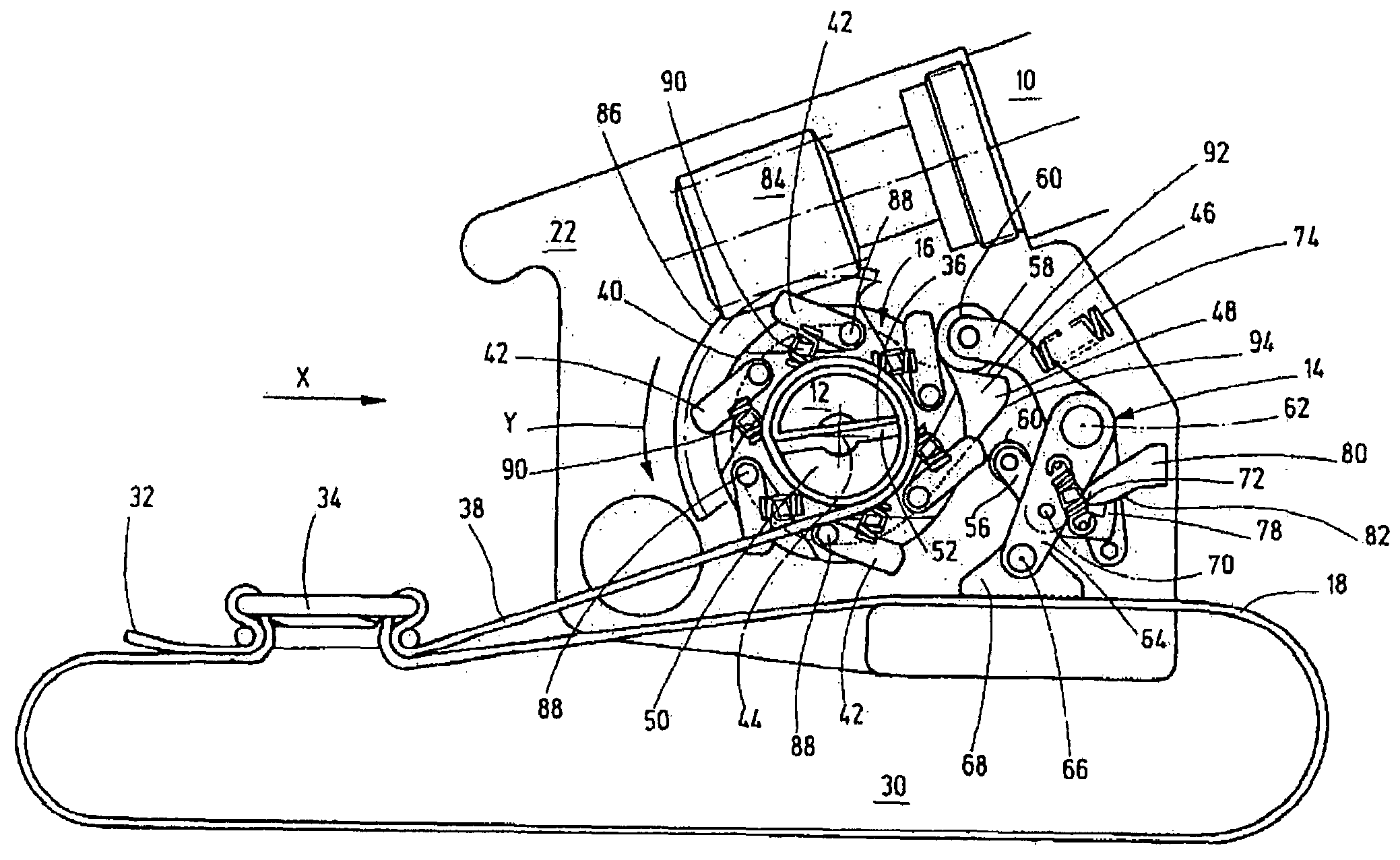
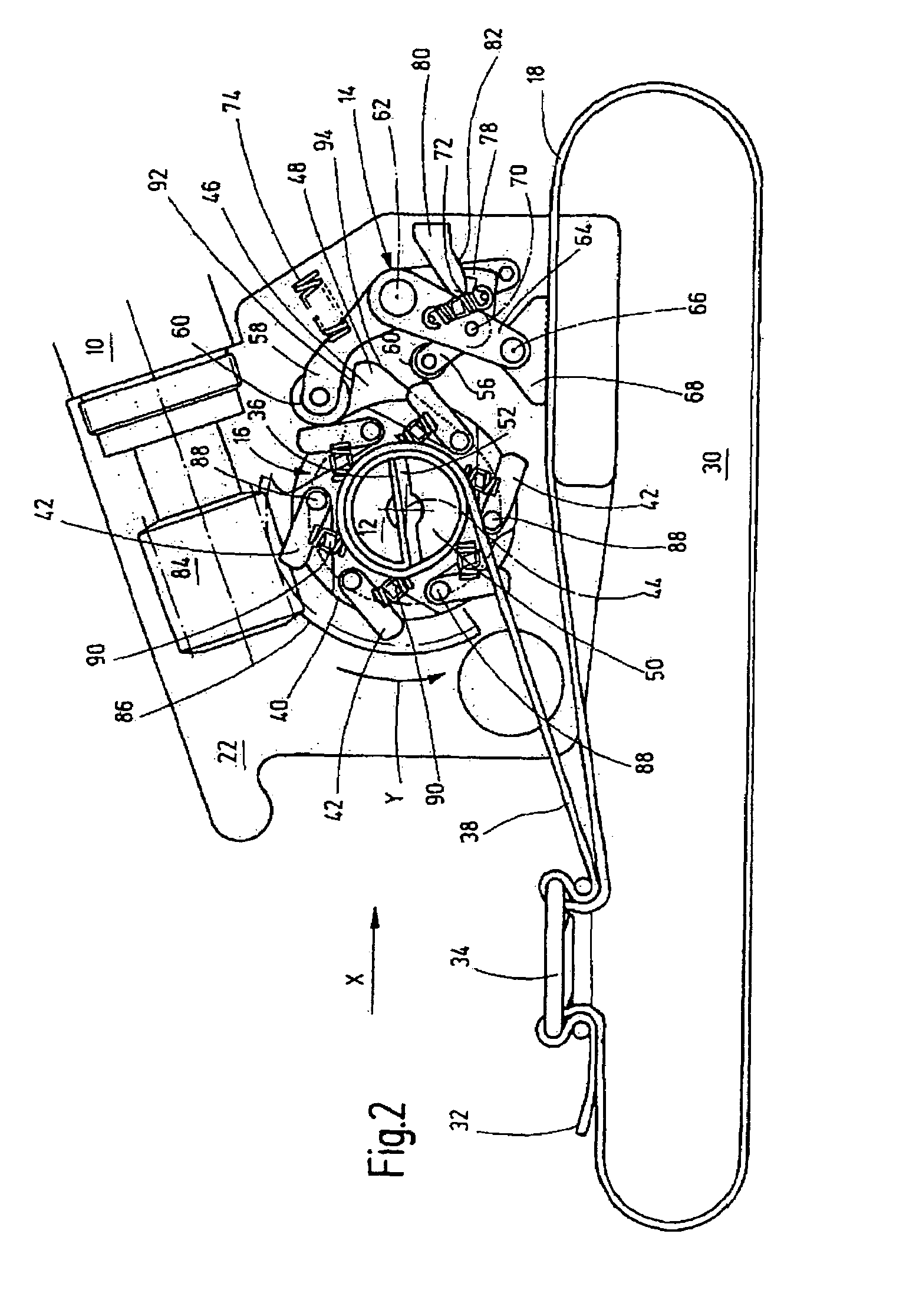
[0026]The control cams 42 (a total of six) of the first control part 40 are arranged at discrete distances from one another extending along the closed curve path extending concentrically to the winding shaft 50. In this first embodiment, the control cams 42 are movable around a pivoting axis 88 against the action of another energy storage device in the form of compression springs 90. A different number of control cams 42 is possible. In this respect, the pivoting control cams 42 are held in at least the direction of rotation Y of the winding shaft 50 in the trigger position for parts of the lever drive in the form of the curve roller 60 of the angle lever 56. The second control part 46, as already described, has a control cam 48 forming on the outer peripheral side an involute path with control flanks 92, 94 tapering conically to its free end. Control flank 92 forms an abutment surface for parts of the lever drive in the form of a curve roller 60 for the upper angle lever 58.

[0027]T...

second embodiment

[0037]In the second embodiment shown in FIGS. 10 to 13, the disk-shaped control part 40 interacting with the winding shaft 50 is equipped with stationary control cams 42a instead of the spring-loaded, movable control cams 42. To achieve the same action as described above, in addition to the angle lever 56, another angle lever 108 is provided having the same pivoting axis 70 as the lever 56. The free end of angle lever 108 overlaps the other angle 56 in the region of the contact flank 78 on the end side with an overlap piece 110 (cf. FIG. 12). In this contact position, the angle lever 108 is held via another tension spring 112. The overlap piece 110 ensures that the angle lever 56 with its contact surface 78 can extend underneath, engaging the stationary catch support 80, according to the foregoing description (cf. FIG. 13).

third embodiment

[0038]In the third embodiment shown in FIGS. 14 to 17, the control disk as the first control part 40 connected securely to the latter, viewed in the direction of FIGS. 14 and 16, has control cams 42b projecting to the rear. If, as already described, the drive unit 10 is turned on, the direction of rotation Y is to result and the winding shaft 50 turns counterclockwise. The control disk is the driver disk 114 permanently connected to the winding shaft 50. An actuating disk 116, pivotally guided on the winding shaft by a conventional bearing site 118 provided with freewheeling, has a spring-loaded actuating pin 120. Viewed in the direction of FIGS. 14 and 15, actuating pin 120 keeps a projecting actuating journal 122 in contact with the projecting, underlying stationary control cam 42b. When the actuating disk 116 continues to be pivoted in the direction of rotation Y, the actuating pin 120 comes into contact with a control housing part 124, and, as shown in FIGS. 16 and 17, is presse...


PUM


Abstract

An apparatus for tensioning a band, in particular a strapping device, includes a drive unit (10) which, in the operated state, drives a band winding unit (12) selectively in opposite directions of rotation. As a result of the band (18), which can be inserted into the apparatus, being releasably locked in predefinable positions by an operating device (14) actuated by a control device (16) of the band winding unit (12), functional positioning of the band winding unit is started to fix the band. The band can be inserted into the apparatus, in the tensioned or tautened state to then be able to insert the band tensioning apparatus for a new strapping operation after the band is severed.

Description

FIELD OF THE INVENTION[0001]The present invention relates to an apparatus for tensioning a band, in particular a strapping device. The apparatus has a drive unit which, in the actuated state, drives a band winding unit selectively in one of opposite directions of rotation.BACKGROUND OF THE INVENTION[0002]Band tensioning apparatus and strapping devices are readily available on the market in a plurality of embodiments. The known solutions, however, have been found to be difficult to manage in manual use, whether due to their dimensions or due to their weight in use. The known solutions are also to some extent costly to produce and are fault-susceptible in operation due to their construction.SUMMARY OF THE INVENTION[0003]An object of the present invention is to develop an apparatus for tensioning a band allowing economical production, being reliable and being easily handled in use with reduced geometrical dimensions.[0004]This object is basically achieved by an apparatus with an actuat...

Claims


Application Information

Patent Timeline
Patent Type & Authority Patents(United States)
IPC IPC(8): B65B13/22B65B13/16
CPCB65B13/185B65B13/22B65B13/345
Inventor FAY, ADOLF
Owner GREINER GMBH & CO KG
Why Eureka
Try Eureka