Electrical connection apparatus and method for an airbag inflator

an airbag and electrical connection technology, which is applied in the direction of coupling device connection, pedestrian/occupant safety arrangement, vehicular safety arrangement, etc., can solve the problems of inability to fully automate production, etc., to achieve convenient electrical connection, economic production, and reliable operation

Inactive Publication Date: 2006-02-28
AUTOLIV ASP INC
View PDF19 Cites 28 Cited by
  • Summary
  • Abstract
  • Description
  • Claims
  • Application Information

AI Technical Summary

Benefits of technology

[0012]The apparatus and method of the present invention have been developed in response to the present state of the art, and in particular, in response to the problems and needs in the art that have not yet been fully solved by currently available airbag inflators and related hardware and methods. Thus, it is an overall purpose of the present invention to provide an airbag inflation apparatus and method that provides for economical production, easy electrical connection, and reliable operation after assembly.
[0013]According to one embodiment, an inflator according to the invention is incorporated into an airbag module. The airbag module may optionally be an inflatable curtain module, or IC module, with an inflatable cushion configured to activate to shield a vehicle occupant from impact against a lateral surface of the vehicle, such as a door or window. The cushion preferably has at least one protection zone, and may optionally have multiple protection zones, each of which may serve to protect one occupant. Thus, a single cushion may, for example, cover a rear door or surface as well as a front door, so that an occupant of a back seat can be protected as well as an occupant of a front seat. The protection zones may be connected by a central tether configured to convey tension and inflation gas between the protection zones.

Problems solved by technology

Unfortunately, such techniques can be quite time consuming and labor intensive.
Thus, fully automated production is not feasible.
However, such sealing devices add expense to the inflator.
Furthermore, such additional sealing parts may accidentally be omitted during assembly.
Unfortunately, many known connectors must be oriented prior to assembly.
However, such connectors typically include no feature to prevent rotation of the connector after assembly.
This rotation may produce undesirable noise or abrade away the conductive surfaces within the connector or the inflator, thereby endangering the integrity of the electrical connection.
Furthermore, many known inflators have comparatively expensive interlock mechanisms designed to receive the associated connector.
Such interior features must often be produced through methods such as machining, and are therefore time and labor intensive to produce.
Such costs add significantly to the overall cost of the inflator.

Method used


Image

  • Electrical connection apparatus and method for an airbag inflator
  • Electrical connection apparatus and method for an airbag inflator
  • Electrical connection apparatus and method for an airbag inflator

Examples


Embodiment Construction

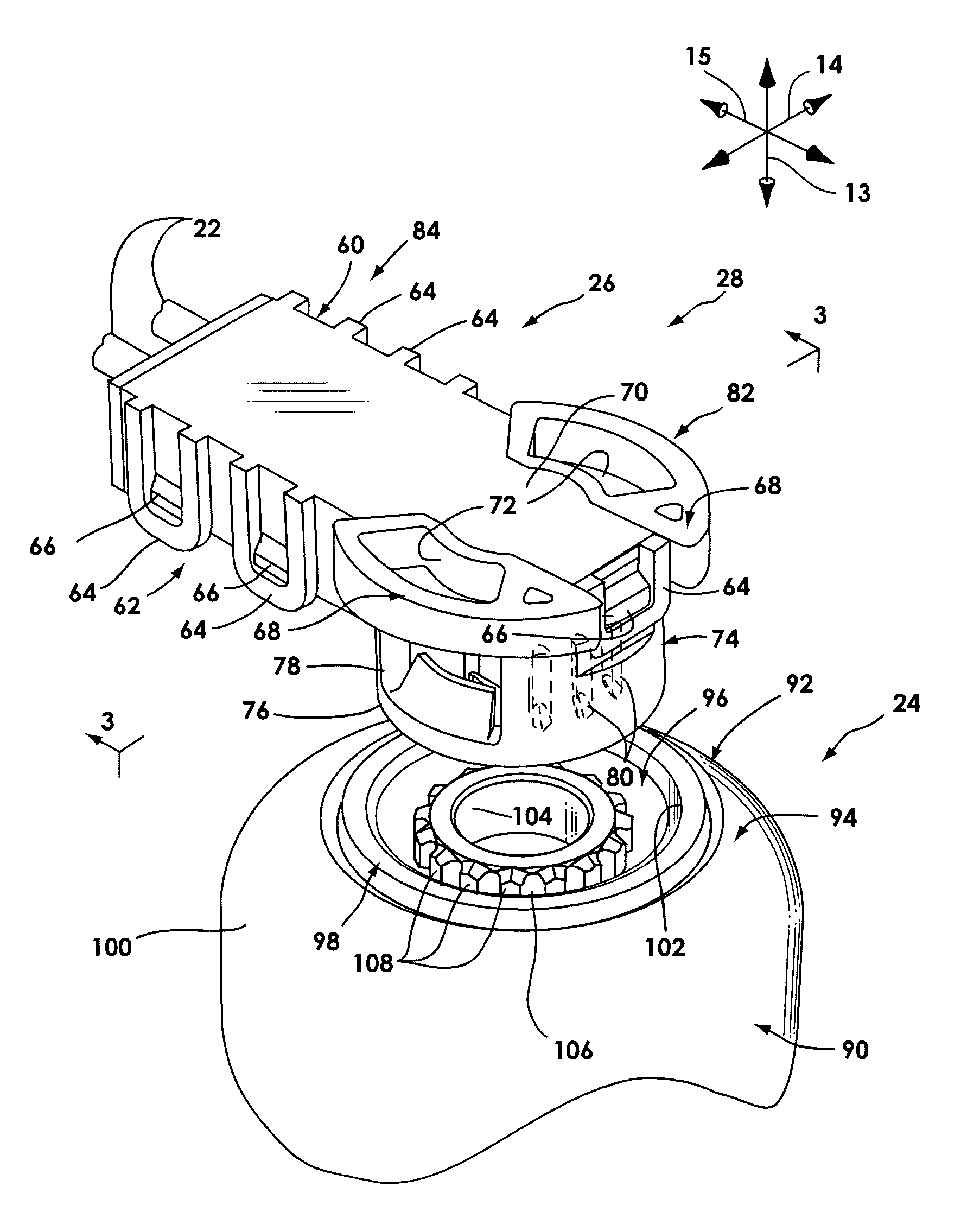
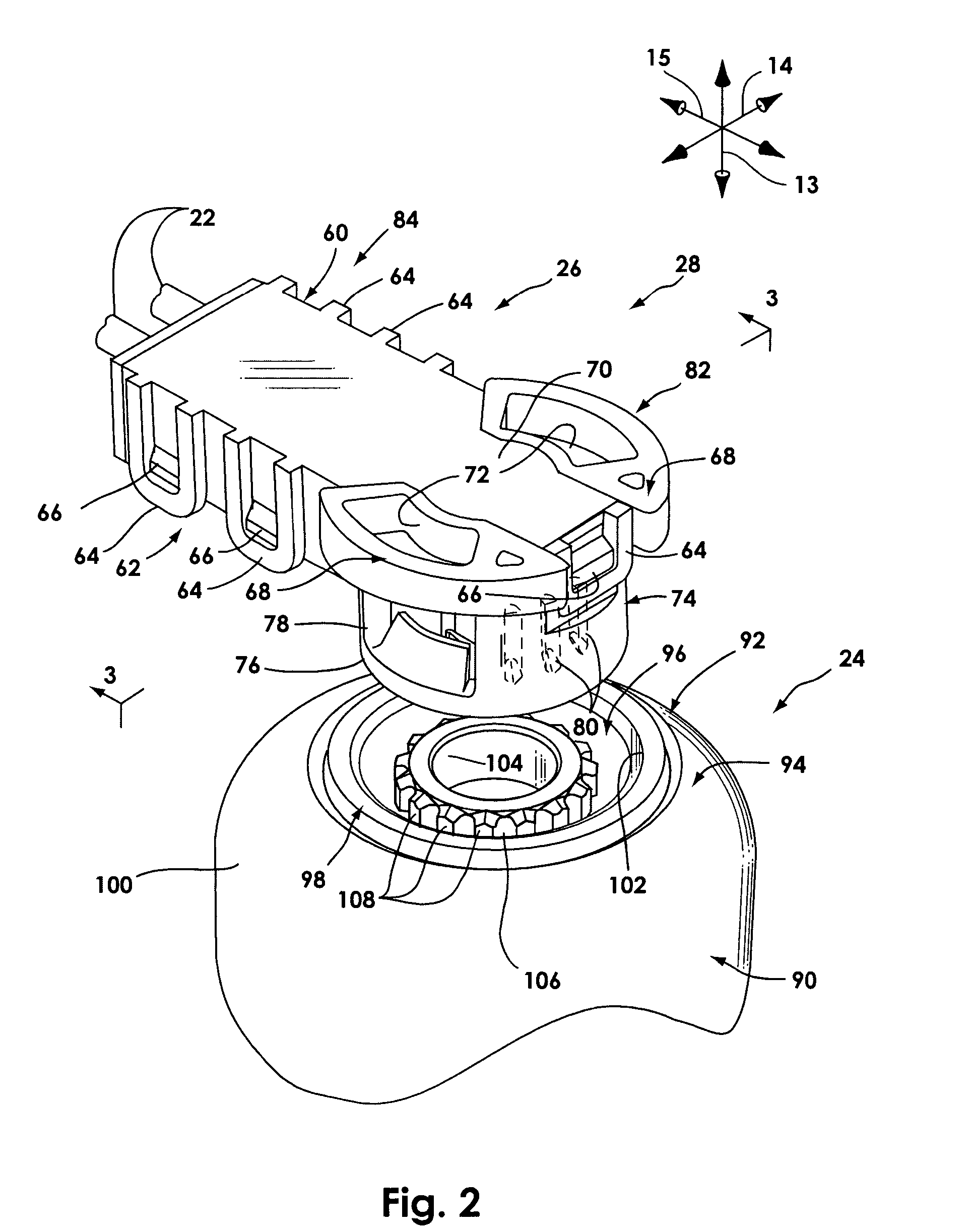
[0097]The presently preferred embodiments of the present invention will be best understood by reference to the drawings, wherein like parts are designated by like numerals throughout. It will be readily understood that the components of the present invention, as generally described and illustrated in the figures herein, could be arranged and designed in a wide variety of different configurations. Thus, the following more detailed description of the embodiments of the apparatus, system, and method of the present invention, as represented in FIGS. 1 through 19e, is not intended to limit the scope of the invention, as claimed, but is merely representative of presently preferred embodiments of the invention.

[0098]The present invention utilizes a number of different principles to enhance the cost-effectiveness, electrical connectability, and reliability of inflators. Through the use of the present invention, labor intensive processes such as insert molding and machining may be reduced or...


PUM


Abstract

An airbag module has an inflator activated via an electrical connector. The inflator includes an initiation assembly having an initiator and a receptacle that retains the connector. The initiator may have a single, center pin. The initiator may be encased by a body and cover, which may be attached together by molding, vibratory welding, electromagnetic welding, or snap fitting. The connector may have projections that extend from a main body to facilitate retention of the connector by a collar, washer, a retainer attached to the body, or by the inflator housing. The body may be seated in a collar having an annular ridge that presses into the body to form a seal. The connector may have a rib designed to mesh with splines of the receptacle to enable engagement of the connector with the receptacle in multiple orientations, while preventing relative rotation between the connector and the initiator after assembly.

Description

BACKGROUND OF THE INVENTION[0001]1. Field of the Invention[0002]The present invention relates to systems and methods for protecting vehicle occupants from injury. More specifically, the present invention relates to inflators and associated electrical connectors for airbag systems.[0003]2. Description of Related Art[0004]The inclusion of inflatable safety restraint devices, or airbags, is now a legal requirement for many new vehicles. Airbags are typically installed in the steering wheel and in the dashboard on the passenger side of a car. In the event of an accident, an accelerometer within the vehicle measures the abnormal deceleration and triggers the expulsion of rapidly expanding gases from an inflator. The expanding gases fill the airbags, which immediately inflate in front of the driver and passenger to protect them from impact against the windshield.[0005]Side impact airbags such as inflatable curtains and seat mounted airbags have also been developed in response to the need ...

Claims


Application Information

Patent Timeline
Patent Type & Authority Patents(United States)
IPC IPC(8): H01R13/627H01R13/62B60R21/26B60R21/264H01R13/58H01R13/631
CPCH01R13/631H01R13/627B60R21/2644B60R2021/26029H01R13/5841
Inventor BARKER, KENTKIDA, JEFFBRISIGHELLA, DARIOPARKS, BRENT
Owner AUTOLIV ASP INC
Why Eureka
Try Eureka