

Power supply unit
- Summary
- Abstract
- Description
- Claims
- Application Information
AI Technical Summary
Benefits of technology
Problems solved by technology
Method used
Image

Examples
Embodiment Construction
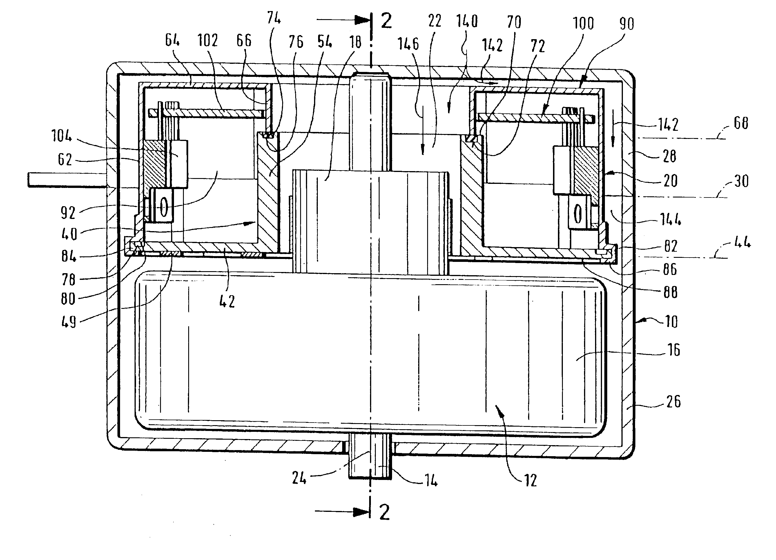
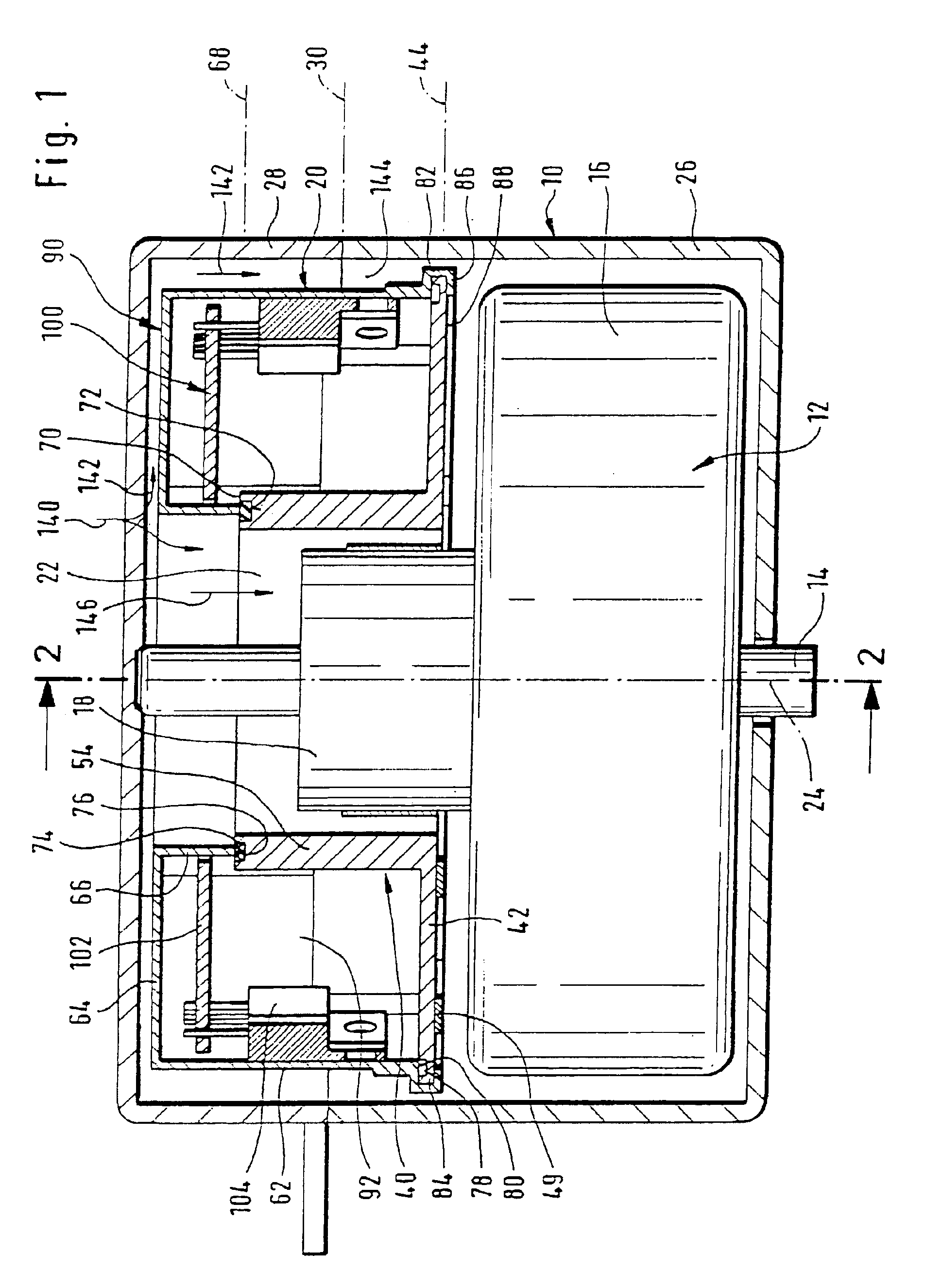
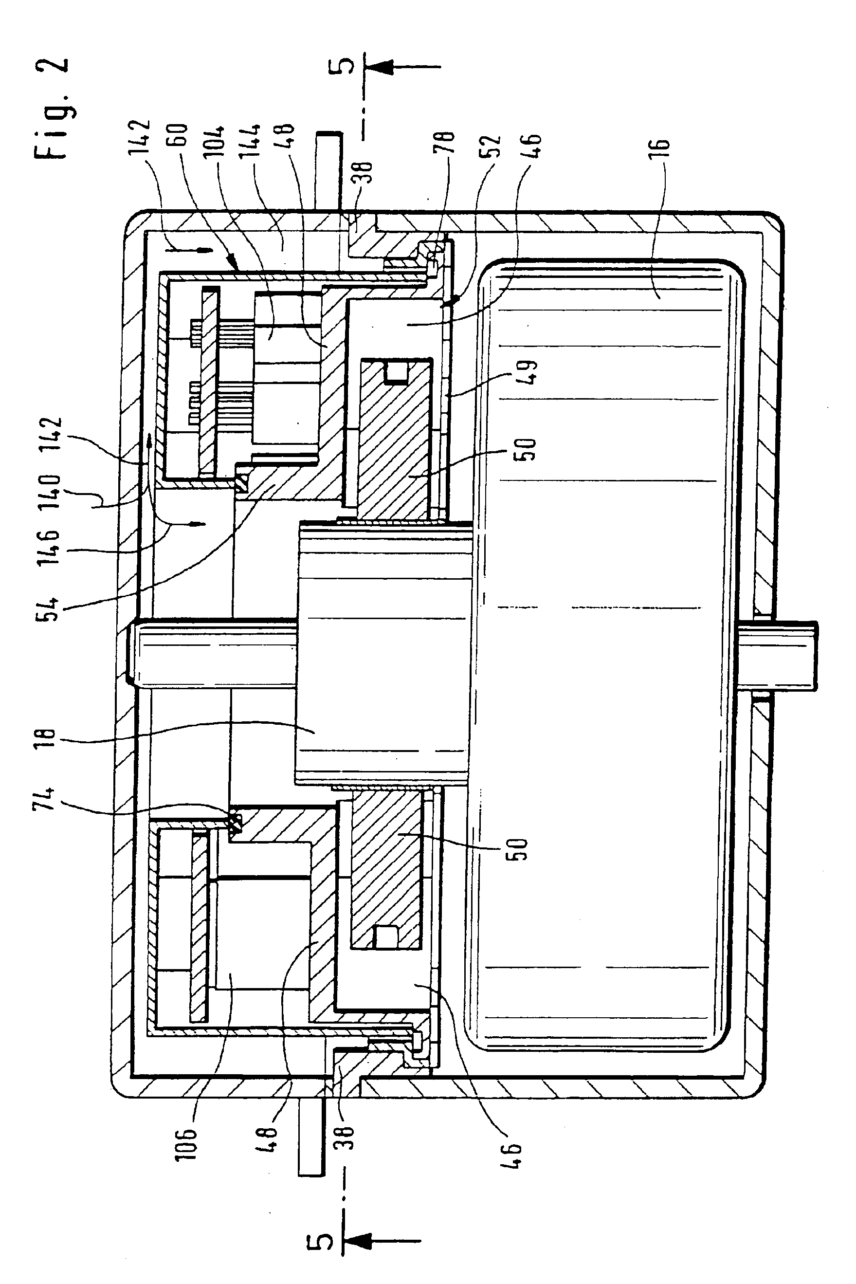
[0070]One embodiment of an inventive drive motor, for example, a fan motor, illustrated in FIGS. 1 to 4, comprises a motor housing 10, in which a rotor 12 with a rotor shaft 14 is mounted so as to be rotatable.
[0071]The rotor 12 comprises an armature 16 seated on the shaft 14 and a commutator 18 which is arranged on one side of the armature 16 and via which power is supplied by armature windings of the armature 16 which are not illustrated.
[0072]A power supply unit designated as a whole as 20 is provided in the motor housing 10 for supplying power to the commutator 18 and this unit preferably extends in an annular shape around a receiving chamber 22 for the commutator 18, wherein the receiving chamber 22 passes through the entire power supply unit 20 in the direction of an axis of rotation 24 of the rotor shaft 14.
[0073]The motor housing 10 is preferably designed in two parts and comprises an armature housing 26 and a housing cover 28 which are separated from one another by a plane ...
PUM
 Abstract
Description
Claims
Application Information