

Roller bearing
a roller bearing and roller bearing technology, applied in the direction of bearings, shafts and bearings, rotary machine parts, etc., can solve the problems of unsatisfactory oil film formation, and achieve the effect of improving the ability to form oil film
- Summary
- Abstract
- Description
- Claims
- Application Information
AI Technical Summary
Benefits of technology
Problems solved by technology
Method used
Image

Examples
Embodiment Construction
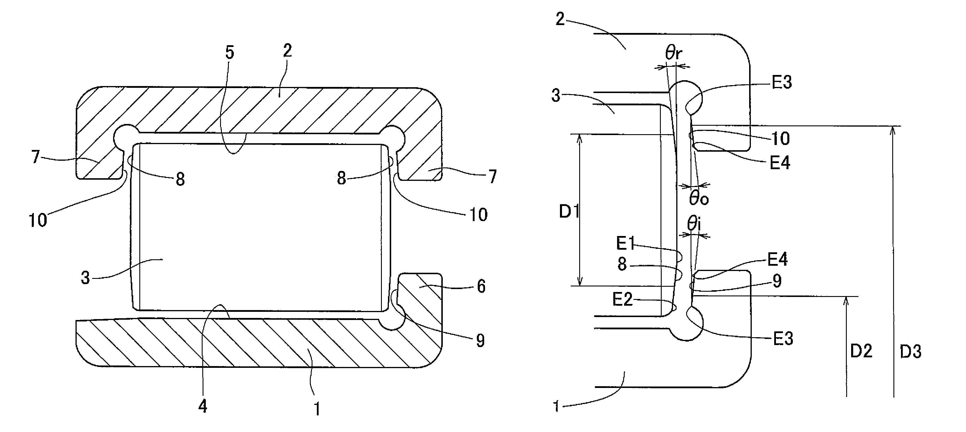
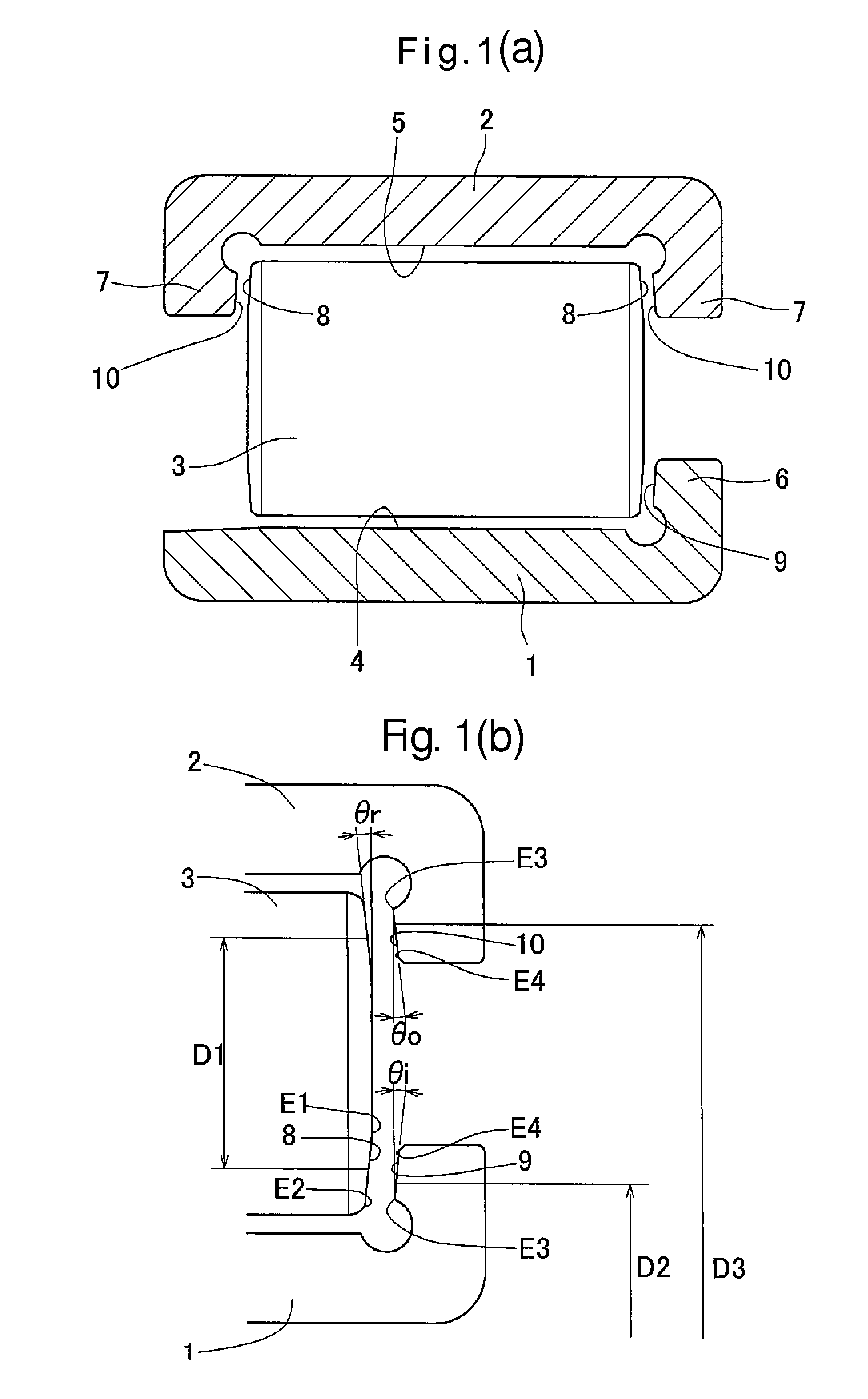
[0029]A roller bearing (hereinafter simply referred to as the “bearing”) according to a first embodiment of the present invention is described with reference to the drawings. As shown in FIG. 1(a), this bearing includes an inner race 1, an outer race 2, and a plurality of rollers 3.
[0030]The inner race 1 is an annular member formed with a raceway 4 and a first flange 6. The outer race 2 is an annular member formed with a raceway 5 and second flanges 7. The first flange 6 and the second flanges 7 are hereinafter simply referred to as the “flange 6” and the “flanges 7”, respectively. The flanges 6 and 7 may comprise flange rings.
[0031]The rollers 3 are cylindrical rollers.
[0032]A thrust load applied rightwardly in FIG. 1 to the bearing can be received by the flange 6, which is on one side of the inner raceway 4, and the right-hand one of the flanges 7, which are on both sides of the outer raceway 5. A thrust load applied leftwardly in FIG. 1 to the bearing can be received by the left-...
PUM
 Abstract
Description
Claims
Application Information