Truck loading device

a technology for loading devices and trucks, which is applied in the direction of loading/unloading vehicle arrangment, transportation items, and removing refuse, etc. it can solve the problems of reducing affecting the service life of the bed, so as to reduce the pitch of the load, reduce the impact of the load, and reduce the impa

Inactive Publication Date: 2015-04-21
DIEZIGER HELEN IRENE
View PDF30 Cites 8 Cited by
  • Summary
  • Abstract
  • Description
  • Claims
  • Application Information

AI Technical Summary

Benefits of technology

[0007]It is accordingly an object of the present invention to use a structure supported by stiff legs to carry the weight of a load until the load is substantially transferred into the truck bed. It is a further object to use a winch and cable system as a means for transferring the load. It is a further object to minimize the pitch of the load at the point of tipping onto the supporting structure, thereby requiring less winch power. It is a further object to provide a platform for assembling a load on the ground. It is a further object to provide said platform with sufficient rigidity to cantilever weight over the supporting structure. It is a further object to allow the truck bed to move independently from the supporting structure while recoiling from the load burden. It is a further object to provide a loading apparatus which can be disassembled into component parts for portability.
[0009]In a preferred embodiment, the means for drawing comprises a first winch and cable system attached between the bed and the pallet. The preferred embodiment further comprises a means for unloading, wherein the means for unloading comprises a second winch and cable system attached between the brace and the front of the pallet. The means for unloading further comprises an at least third stiff leg placed centrally with respect to the crossbar, the at least third stiff leg serving to operationally direct the cable of the second winch and cable system while providing a vertical rail to prevent the pallet from diving beneath the crossbar. The preferred embodiment still further comprises a means for minimizing the tipping moment of the pallet over the crossbar while pivoting there upon, the means for minimizing the tipping moment comprising an extension to the pallet perpendicular to the crossbar, the extension essentially reducing the angle of attack to the crossbar.

Problems solved by technology

Loading a truck bed, such as on a pickup truck, sometimes involves heavy or unwieldy lifting in a situation where mechanized equipment is unavailable for the task.
Another case can be made for aggregated loads, such as firewood, shingle bundles, building blocks, or soil, fertilizer, or salt in bags, where lifting individual pieces one-at-a-time would be inefficient.
The platform and associated hydraulics, however, must be installed in the truck, rendering the bed thereby unusable for other purposes.
At the tail, in such an extreme position, the forces are applied against the suspension and the frame with damaging leverage.
In spite of the temporary supporting role of the stiff legs, they are ultimately rendered ineffective in preventing weight from being applied to the tail in a potentially damaging way.

Method used


Image

  • Truck loading device
  • Truck loading device
  • Truck loading device

Examples


Embodiment Construction

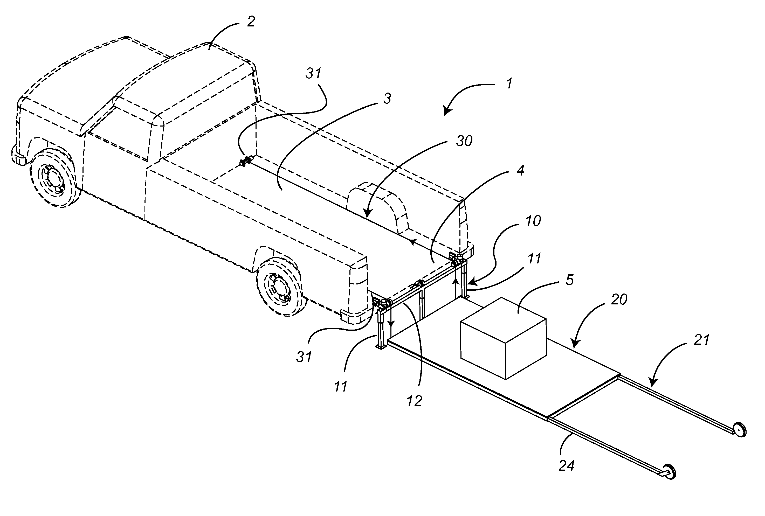
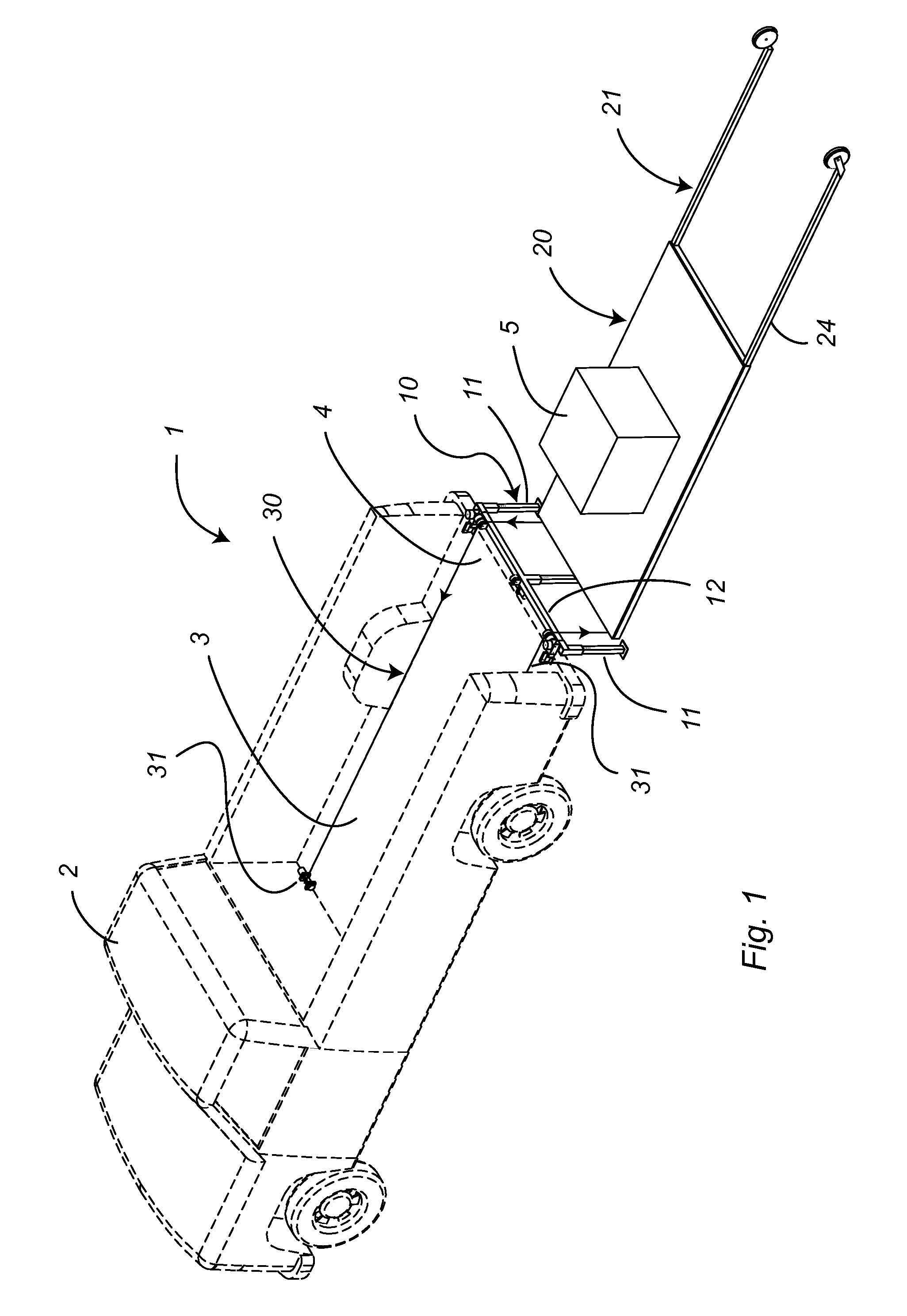
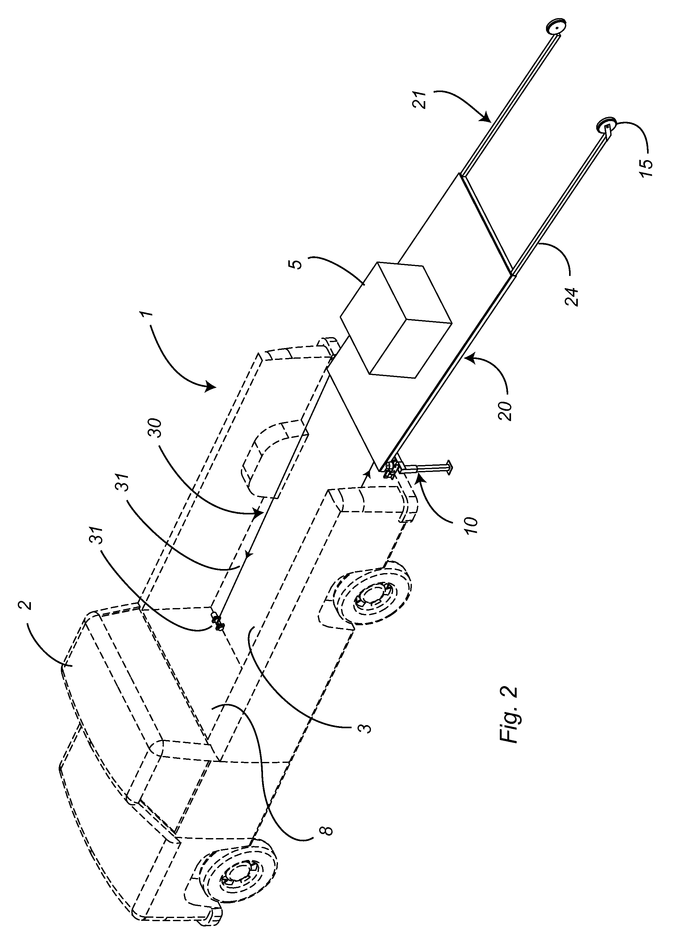
[0018]The constituent components of the present invention are best shown in FIGS. 1 and 2. An apparatus for loading 1 a load 5 onto a truck 2 having a truck bed 3 with an open end 4 is comprised of a brace 10, a pallet 20 on which the load 5 is placed, and a means for drawing 30 the loaded pallet 20 over the brace 10 and onto the truck bed 3.

[0019]In the preferred embodiment, the means for drawing 30 is a first winch and cable system 31. The winch is typically located at the end of the truck bed opposite the open end 4 to maximize the length of the draw. In the preferred embodiment, the cable is dead-headed at or near the cab bulkhead 8 such that the winch has a two-to-one purchase in drawing the loaded pallet 20. One or more turning blocks (not shown) may be used on the front end of the pallet to reverse the direction of the cable.

[0020]Referring to FIGS. 1 and 4, the brace 10 is comprised of at least two upright stiff legs 11 joined proximate the top ends thereof by a crossbar 12....


PUM


Abstract

An apparatus for loading the bed of a pickup truck comprises a brace for supporting a load from the ground, the brace preventing the load from applying weight to the tail end of the bed with damaging consequences while being drawn into position by a winch and cable system. A pallet is used to stage the load on the ground and to provide a structure with a low angle of attack to the brace, the low angle of attack facilitating the transition of the load to the bed by reducing the tipping moment over the brace.

Description

FIELD OF THE INVENTION[0001]This invention relates to loading devices for trucks, and more particularly to winch-driven loading devices for pickup trucks.BACKGROUND OF THE INVENTION[0002]Loading a truck bed, such as on a pickup truck, sometimes involves heavy or unwieldy lifting in a situation where mechanized equipment is unavailable for the task. Such a situation might occur in a home or field environment. Such a case can be made for snowmobiles, four-wheeled recreational vehicles, boats, game carcasses, or camper-inserts, to name a few objects which are too large or too heavy for manual manipulation. Another case can be made for aggregated loads, such as firewood, shingle bundles, building blocks, or soil, fertilizer, or salt in bags, where lifting individual pieces one-at-a-time would be inefficient. In all cases, it is useful to stage the load at ground level and use a portable device to lift and transfer the load onto the truck bed.[0003]A winch and cable system powered by a b...

Claims


Application Information

Patent Timeline
Patent Type & Authority Patents(United States)
IPC IPC(8): B60P1/00B60P1/14B60P1/43B60P1/64
CPCB60P1/433B60P1/6427B60P1/14
Inventor DIEZIGER, DAVID DOUGLAS
Owner DIEZIGER HELEN IRENE
Why Eureka
Try Eureka