
Cushion device for track loader and track loader having same

a suspension device and track loader technology, applied in endless track vehicles, vehicles, constructions, etc., can solve the problems of frequent damage increased driver's fatigue, and increased shocks to be continuously applied to the track loader body while the track loader is being used

Inactive Publication Date: 2018-08-23
DEERE & CO
View PDF6 Cites 0 Cited by
  • Summary
  • Abstract
  • Description
  • Claims
  • Application Information

AI Technical Summary

Benefits of technology

The present invention provides a suspension device for a track loader and a track loader having the same that can solve the problem of lowered workability and rising comfort caused by the rotation of the link housing mounted on the front side of the bogie frame in opposite direction to the rotating direction of the link housing mounted on the rear side of the bogie frame. The technical effects of the invention are stable release of shocks during work and driving of the track loader, reducing fatigue of the driver, minimizing damages of the body, and enhancing the workability and rising comfort of the track loader. Additionally, the link housing mounted on the front side of the bogie frame rotates in the same direction as the link housing mounted on the rear side of the bogie frame, minimizing the pitching of the body generated during work and driving of the track loader.

Problems solved by technology

On the other hand, the track loader is driven by means of bogies using caterpillar tracks, so that the track loader is usually driven on severe hills or rough places, rather on flat places, which causes lots of shocks to be continuously applied to the track loader body while the track loader is being driven or working.
As a result, a driver's fatigue becomes seriously increased, and also, damages frequently occur on the track loader body.
According to the conventional suspension device for the track loader, however, when the axle is coupled to the track loader body through the connection with a bracket, it becomes distant from the bucket so as to prevent the interference between the bracket and the bogie frame, thereby undesirably losing the balance of the system.
As a result, stopping, starting, and bucket elevating of the track loader are all carried out unstably, thereby causing the track loader body to be seriously vibrated and lowering the workability and riding comfort thereof.
Up to now, however, no results for satisfying such need have been suggested.

Method used


Image

  • Cushion device for track loader and track loader having same
  • Cushion device for track loader and track loader having same
  • Cushion device for track loader and track loader having same

Examples


Embodiment Construction

[0038]Hereinafter, an explanation on a suspension device for a track loader according to the present invention will be in detail given with reference to the attached drawings.

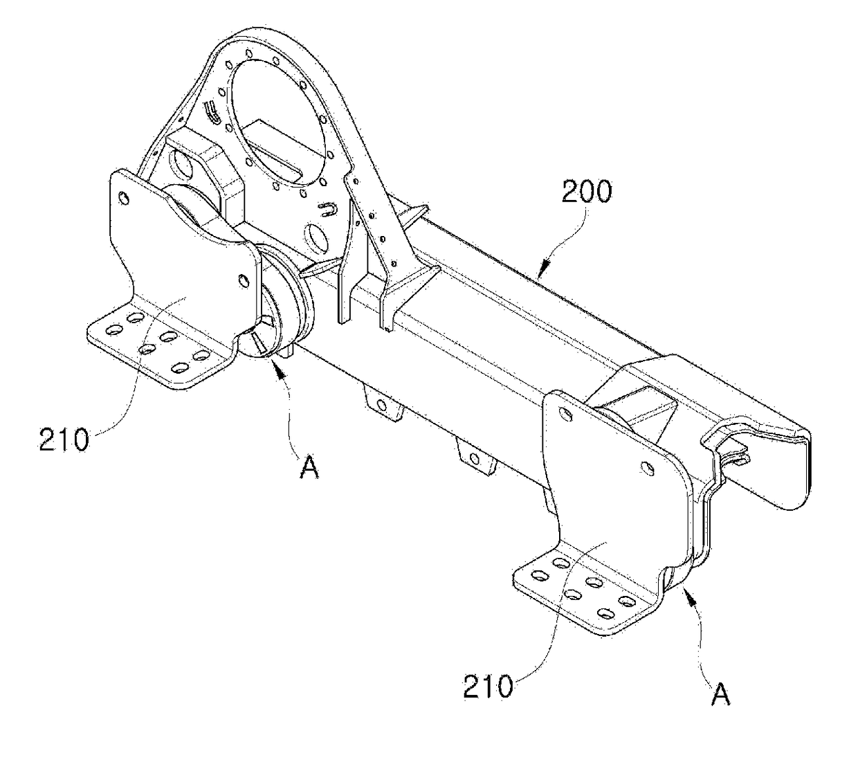
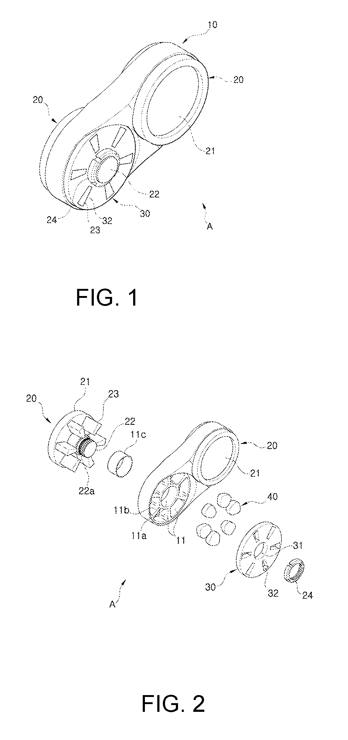
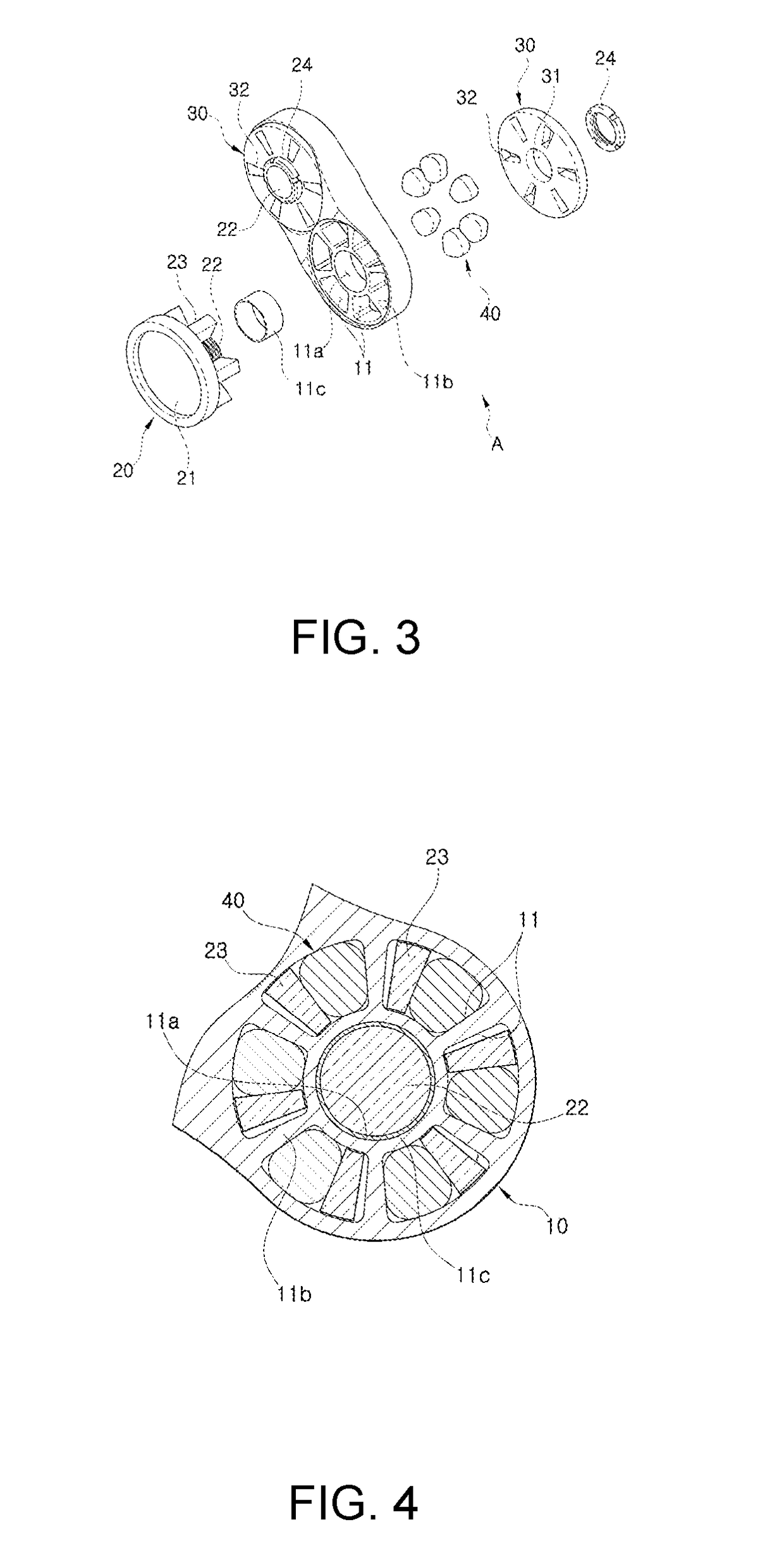
[0039]As shown in FIGS. 1 to 3, a suspension device A for a track loader according to the present invention includes a link housing 10, a pair of axles 20, a pair of covers 30, and a plurality of buffering members 40.

[0040]The link housing 10 has a pair of axis holes 11a spaced apart from each other in left and right directions thereof and a plurality of openings 11 formed radially along each axis hole 11a.

[0041]At this time, the openings 11 are formed by means of partition walls 11b radially formed along each axis hole 11a.

[0042]As the openings 11 are formed by means of the partition walls 11b, a plurality of protruding plates 23 of each axle 20 and the plurality of buffering members 40, are insertedly fitted to the openings 11 in such a manner as to be separable from each other.

[0043]In this case, each axis...


PUM


Abstract

A suspension device for a track loader and a track loader having the same are provided that are capable of releasing the shocks applied to a body and minimizing the pitching of the body generated during the work and driving of the track loader to prevent the body from being damaged, reducing a driver's fatigue, and enhancing the workability and rising comfort of the track loader.

Description

TECHNICAL FIELD[0001]The present invention relates to a suspension device for a track loader and a track loader having the same, and more particularly, to a suspension device for a track loader and a track loader having the same that are capable of preventing a track loader body from being damaged, reducing a driver's fatigue while the track loader is being driven, and enhancing riding comfort and workability of the track loader.BACKGROUND ART[0002]A track loader has a bucket, and using the bucket, accordingly, the track loader performs a variety of work such as excavation, soil castle building, soil preparation, and soil, sand or gravels transferring and loading.[0003]Accordingly, the track loader is used widely in various sites of construction, civil engineering, aggregate collection, and the like.[0004]On the other hand, the track loader is driven by means of bogies using caterpillar tracks, so that the track loader is usually driven on severe hills or rough places, rather on fla...

Claims


Application Information

Patent Timeline
IPC IPC(8): B62D55/108B62D55/06
CPCB62D55/1086B62D55/06E02F3/3414B62D55/104E02F9/02
Inventor NAM, YOON TAEJO, CHUL HYEON
Owner DEERE & CO
Learn More