Optical filter and manufacturing method thereof

a technology of optical filter and manufacturing method, which is applied in the field of optical filter, can solve the problems of affecting the performance of the filter, and causing the malfunction of precision devices, so as to improve the light transmittance, and reduce the loss of shielding angle.

Inactive Publication Date: 2010-06-17
SAMSUNG SDI CO LTD
View PDF0 Cites 13 Cited by
  • Summary
  • Abstract
  • Description
  • Claims
  • Application Information

AI Technical Summary

Benefits of technology

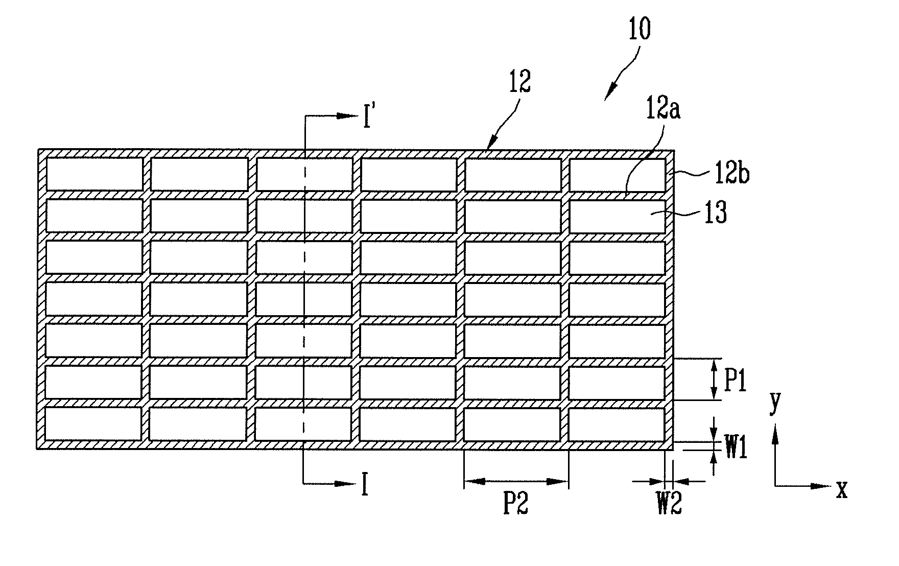
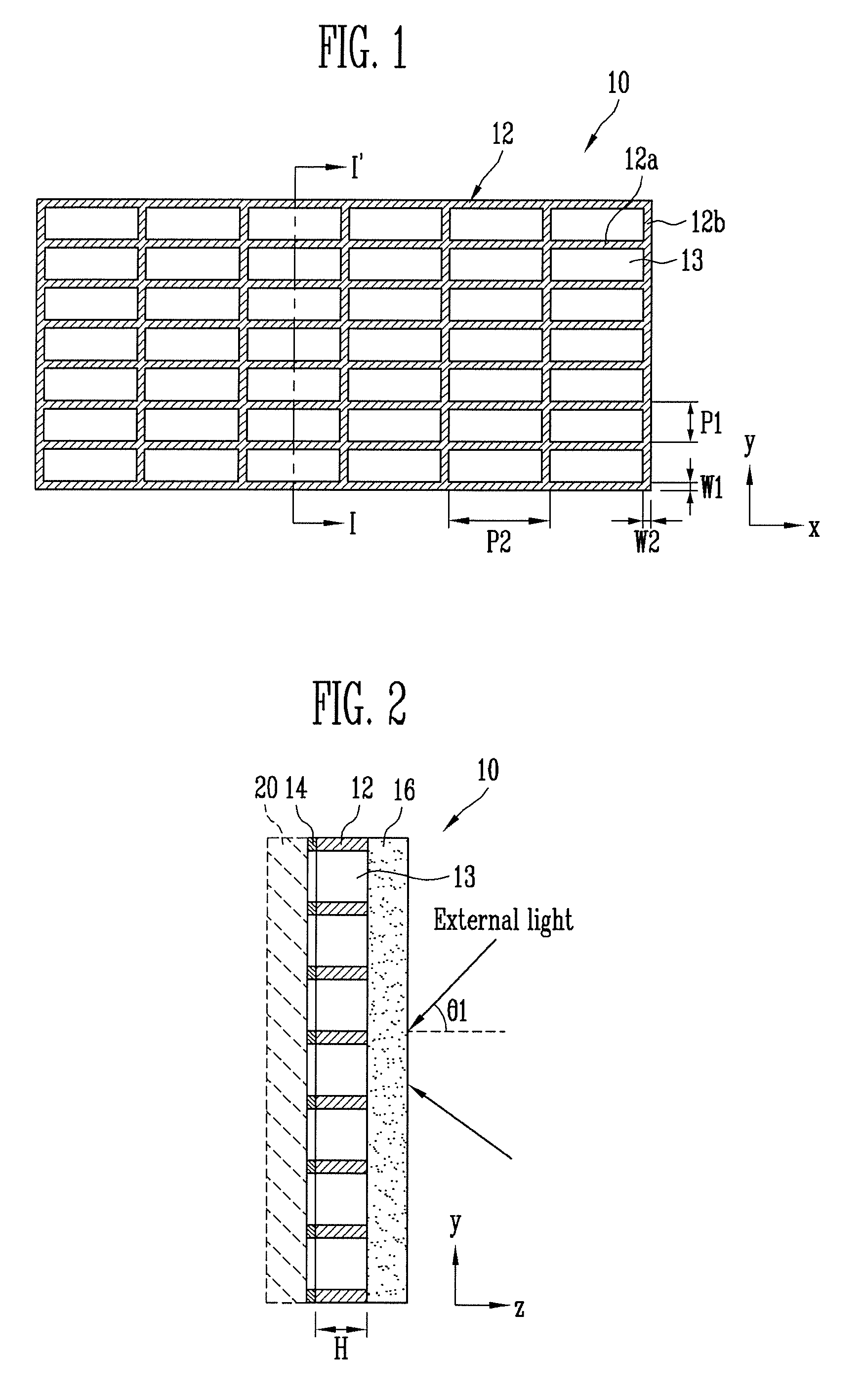
[0010]Accordingly, embodiments of the present invention provide an optical filter wherein an external light shielding layer and an electromagnetic wave shielding layer are integrally formed as a single sheet, so that the pitch between barriers of the external light shielding layers is increased, thereby improving transmittance.
[0011]Embodiments of the present invention also provide a method capable of easily manufacturing the aforementioned optical filter.
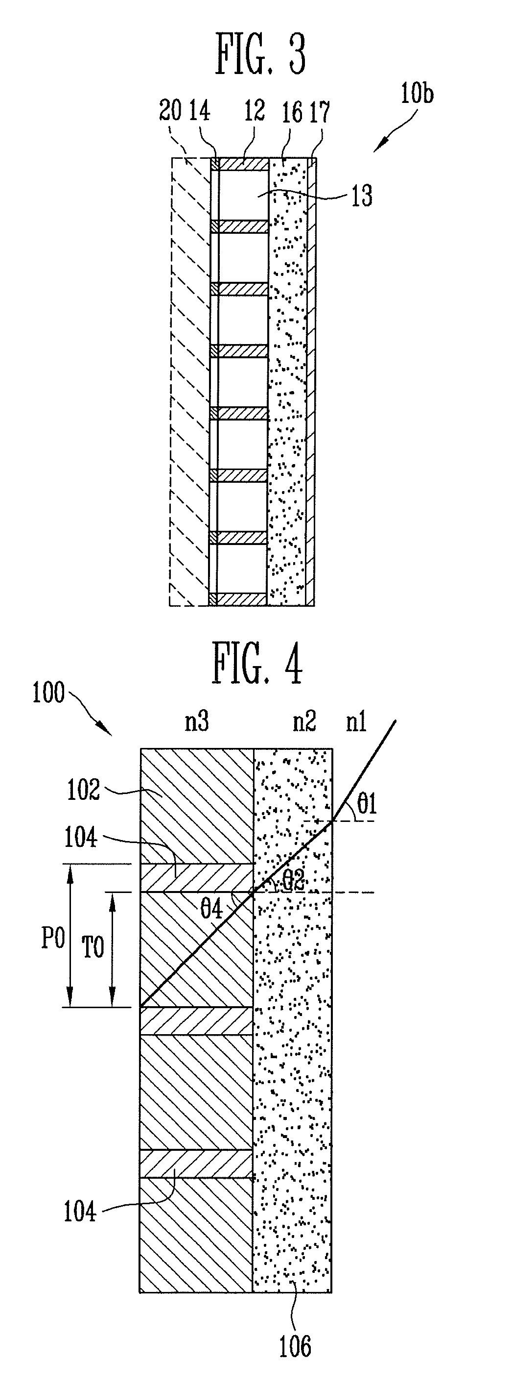
[0023]According to the embodiments of the present invention, a black material for shielding external light and a conductive layer for shielding electromagnetic waves are integrally formed in a single sheet, thereby providing an optical filter in which the pitch of the black material serving as an external light shielding layer is increased, and light transmittance is improved. Further, air or a transparent material having low permittivity fills the openings of the sheet of black material and the conductive layer, thereby minimizing loss of a shielding angle caused by refraction of external light incident onto the optical filter. Accordingly, transmittance of internal light generated and radiated from a plasma display device can be increased, and bright room contrast of the plasma display device can be improved.

Problems solved by technology

Further, the electromagnetic waves and near infrared light, generated in the PDP, are harmful to humans and induce malfunction of precision devices.
Therefore, manufacturing process of a conventional optical filter is complicated and its manufacturing cost is high due to a process of laminating the respective functional layers, and the like.
And when the electromagnetic wave shielding film and the external light shielding film are laminated together, it is very difficult to align the patterns of the two functional films to each other.

Method used


Image

  • Optical filter and manufacturing method thereof
  • Optical filter and manufacturing method thereof
  • Optical filter and manufacturing method thereof

Examples


Embodiment Construction

[0032]In the following detailed description, only certain exemplary embodiments of the present invention have been shown and described, simply by way of illustration. As those skilled in the art would realize, the described embodiments may be modified in various different ways, all without departing from the spirit or scope of the present invention. Accordingly, the drawings and description are to be regarded as illustrative in nature and not restrictive. In addition, when an element is referred to as being “on” another element, it can be directly on the another element or be indirectly on the another element with one or more intervening elements interposed therebetween. Also, when an element is referred to as being “connected to” another element, it can be directly connected to the another element or be indirectly connected to the another element with one or more intervening elements interposed therebetween. Hereinafter, like reference numerals refer to like elements.

[0033]In the f...


PUM

PropertyMeasurementUnit
refractive indexaaaaaaaaaa
widthaaaaaaaaaa
widthaaaaaaaaaa

Abstract

An optical filter for a plasma display device with improved shielding angle and transmittance, and a method of manufacturing the optical filter. The optical filter includes an external light shielding layer having a plurality of first openings; and an electromagnetic wave shielding layer integrated with the external light shielding layer on one surface of the external light shielding layer, where the electromagnetic wave shielding layer has a plurality of second openings corresponding to the plurality of first openings.

Description

CROSS-REFERENCE TO RELATED APPLICATIONS[0001]This application claims priority to and the benefit of Korean Patent Application No. 10-2008-0126376, filed on Dec. 12, 2008, in the Korean Intellectual Property Office, the entire content of which is incorporated herein by reference.BACKGROUND OF THE INVENTION[0002]1. Field of the Invention[0003]An aspect of the present invention relates to an optical filter, and more particularly, to an optical filter for a plasma display device, and a method of manufacturing the optical filter.[0004]2. Description of Related Art[0005]A plasma display panel (PDP) is a display device which displays images by generating plasma in a discharge space between two sheets of glass substrates facing each other and exciting phosphors with the generated plasma to emit light.[0006]However, in a PDP, electromagnetic waves are generated by plasma emission and operations of a driving circuit, and near infrared light is generated by discharge of an inert gas in the PDP...

Claims


Application Information

Patent Timeline
Patent Type & Authority Applications(United States)
IPC IPC(8): G02B5/22G03F7/20
CPCG02B2207/123H01J2211/446H01J2211/444H01J11/44G02B5/20H05K9/00
Inventor LEE, JIN-YOUNGLEE, SUNG-YONGKIM, JAE-HYUNG
Owner SAMSUNG SDI CO LTD
Why Eureka
Try Eureka