Method for measuring sheet material flatness and method for producing steel sheet using said measuring method

a technology of flatness and measurement method, which is applied in the direction of measuring devices, instruments, and profile control devices, etc., can solve the problems of insufficient installation space of the device, linear pattern is liable to collapse, etc., to achieve high accuracy, flatness of the sheet material can be measured, and high accuracy

Active Publication Date: 2012-08-16
NIPPON STEEL CORP
View PDF1 Cites 14 Cited by
  • Summary
  • Abstract
  • Description
  • Claims
  • Application Information

AI Technical Summary

Benefits of technology

[0016]The present invention has been made to solve the problems with the prior arts explained above, and accordingly an objective thereof is to provide a method for measuring the flatness of a sheet material such as a steel sheet running in the longitudinal direction, in which even in the case where an image pickup device is arranged at a position at which the specularly reflected light of a light and dark pattern projected onto the surface of a sheet material having a strong specular reflection property can be received, the surface shape of the sheet material can be measured with high accuracy, whereby the flatness of the sheet material can be measured with high accuracy.
[0017]In the case where the light and dark pattern projected onto the surface of a sheet material is made the linear pattern having a small pitch, if the image pickup device is arranged at a position at which the specularly reflected light can be received, as the countermeasures for preventing the collapse of the linear pattern in the picture element region corresponding to the element receiving the specularly reflected light and the peripheral elements, the methods described below are conceivable: (1) a method in which a camera having a wide dynamic range is employed as the image pickup device so that even if the sensitivity of the image pickup device is reduced, the output signal intensity of the element that does not receive the specularly reflected light does not become insufficient, and (2) a method in which the pitch of the linear pattern is increased.
[0020]Accordingly, the present inventors conducted studies earnestly, and hit upon an idea that a staggered pattern shown in FIG. 3C is to be used as the light and dark pattern projected onto the surface of the sheet material, the staggered pattern being composed of light portions arranged in a staggered form at a predetermined preset pitch (preset pitch PL in the longitudinal direction, preset pitch PW in the transverse direction) in the longitudinal direction and the transverse direction, and this pattern is to be projected onto the surface of the sheet material so that the longitudinal direction of the staggered pattern corresponds to the longitudinal direction of the sheet material, and the transverse direction thereof corresponds to the width direction of the sheet material. With this staggered pattern, since the light portions are arranged in a staggered form in the longitudinal direction and the transverse direction, even if the longitudinal preset pitch PL between light portions is equal to the preset pitch PL′ of the conventional linear pattern (FIG. 3A), the distance between the light portions adjacent in the longitudinal direction (for example, light portions M1 and M2) becomes longer (or doubled) than the distance PL′ between the light portions adjacent in the longitudinal direction in the conventional linear pattern, and therefore the space between the light portions increases. Concerning the transverse direction, the light portion is continuous in the conventional linear pattern, whereas in the staggered pattern, the light portions adjacent in the straight-line form in the transverse direction (for example, light portions M1 and M3) have a space therebetween. Therefore, the staggered pattern has an advantage that even in the picture element region corresponding to the element or the like of image pickup device receiving the specularly reflected light, the light and dark pattern is difficult to collapse.
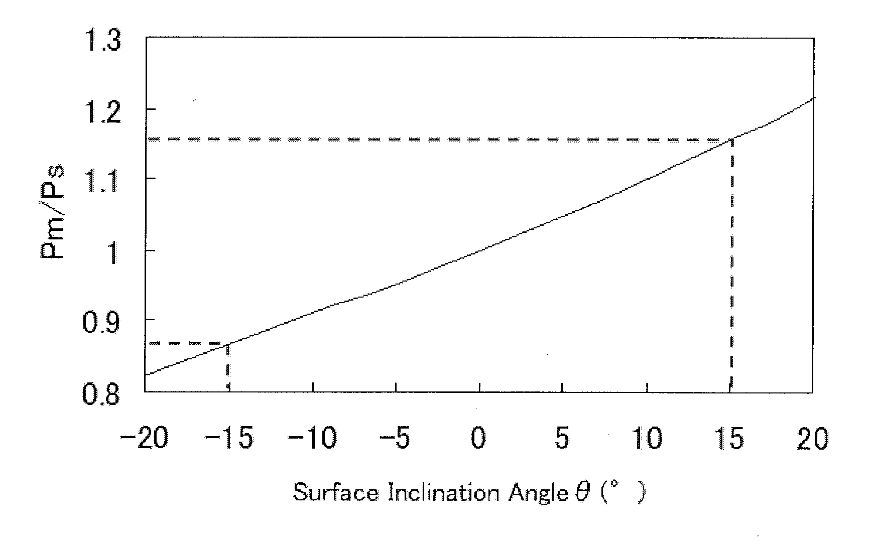
[0023]As explained above, the present inventors reached a conclusion that if the surface shape of the sheet material is calculated by the procedures of items (A) to (C) described below, even in the case where the image pickup device is disposed at a position at which the specularly reflected light of the light and dark pattern projected onto the surface can be received, the light and dark pattern is difficult to collapse, and the surface shape, and therefore the flatness of the sheet material can be measured with high accuracy without a decrease in measurement resolution.

Problems solved by technology

At the location just close to the exit of the finishing mill, a sufficient installation space for the device cannot be secured in many cases because measuring instruments such as a sheet thickness meter, a sheet width meter, and a sheet thermometer are installed, and besides the cooling zone for water cooling is installed just close to this location.
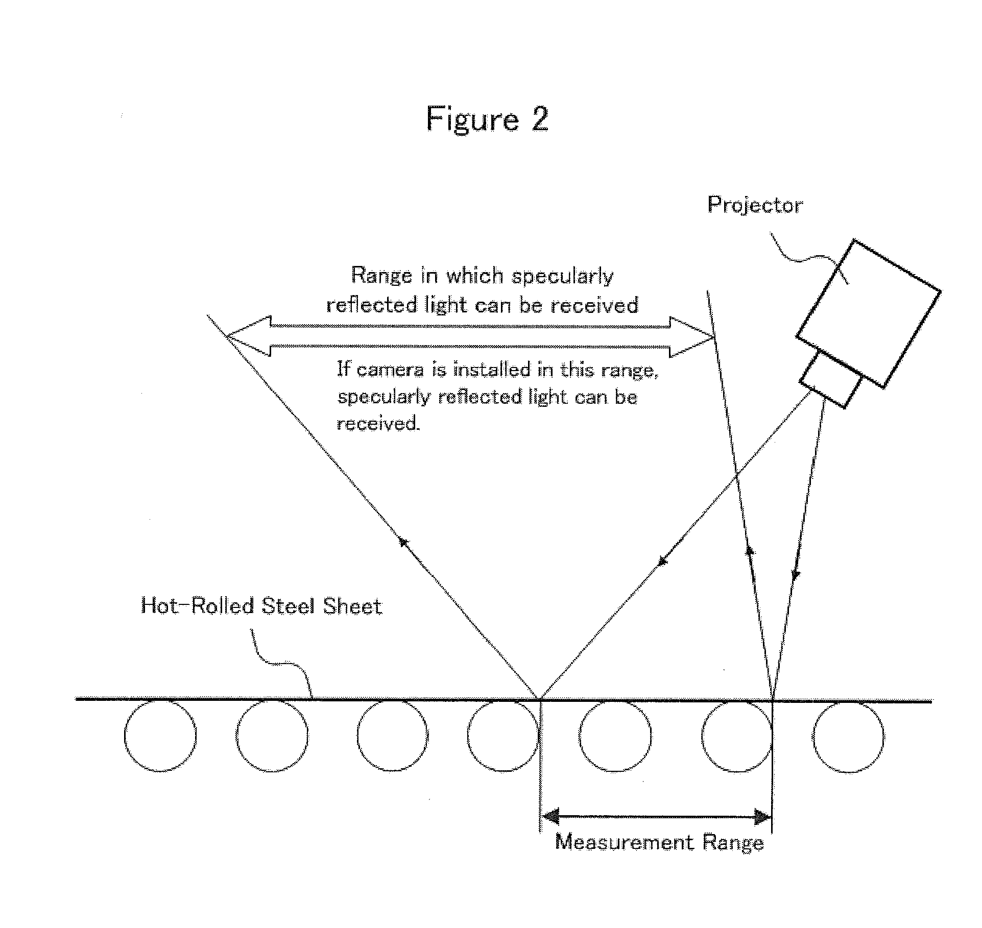
However, since the surface of the hot-rolled steel sheet immediately after being finish rolled has a strong specular reflection property (the reflection intensity of specular reflection component is high), if the camera is arranged at a position at which the specularly reflected light of projected light of the projector can be received, the output signal sent from an element receiving the specularly reflected light of the light receiving elements of the camera saturates, and halation occurs.
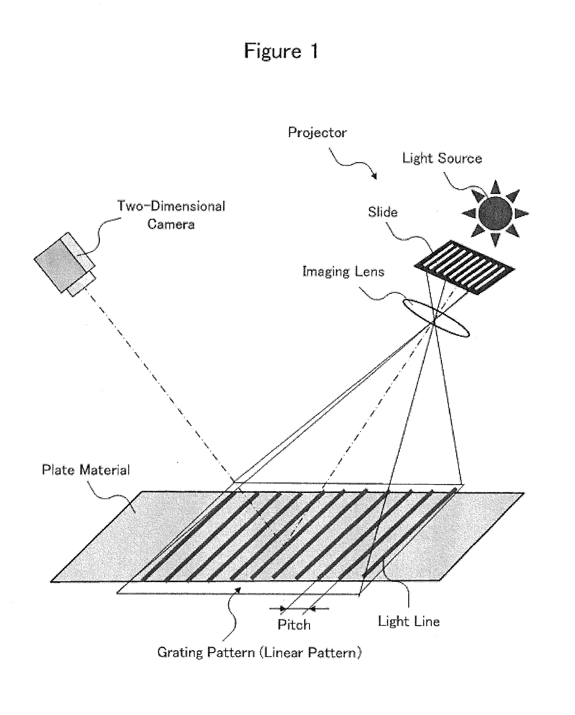
Therefore, in the picture element region of photographed images corresponding to the element receiving the specularly reflected light and the peripheral elements, the adjacent light lines stick to each other, and the linear pattern is liable to collapse.
Also, if the sensitivity of the camera is reduced excessively to prevent the linear pattern from collapsing, the output signal intensity of elements other than the element receiving the specularly reflected light becomes insufficient, so that the concentration of picture element corresponding to the element having an insufficient output signal intensity in the photographed image decreases, and therefore a linear pattern in which the light lines are difficult to distinguish is formed.

Method used


Image

  • Method for measuring sheet material flatness and method for producing steel sheet using said measuring method
  • Method for measuring sheet material flatness and method for producing steel sheet using said measuring method
  • Method for measuring sheet material flatness and method for producing steel sheet using said measuring method

Examples


Embodiment Construction

[0076]One embodiment of the present invention will now be described with reference to the accompanying drawings as appropriate. In the description below, explanation is given by taking as an example the case where the sheet material is a hot-rolled steel sheet, and the flatness (degree of steepness) thereof is measured on the exit of a finishing mill train on a hot-rolled steel sheet production line.

[0077]FIG. 5 is a schematic view showing an outline configuration example of a flatness measuring apparatus for carrying out the flatness measuring method in accordance with the present invention. FIG. 6 is a schematic view showing the installation state of the flatness measuring apparatus shown in FIG. 5. As shown in FIGS. 5 and 6, a flatness measuring apparatus 100 of this embodiment includes a projector 1 for projecting a staggered pattern P, which is a light and dark pattern, onto the surface of a hot-rolled steel sheet S running horizontally in the longitudinal direction so that the...


PUM

PropertyMeasurementUnit
thicknessaaaaaaaaaa
heightaaaaaaaaaa
lengthaaaaaaaaaa

Abstract

A method for measuring flatness of a sheet material in which a light and dark pattern composed by a light portion and a dark portion is projected onto a surface of the sheet material running in a longitudinal direction, a pattern image is acquired by photographing the light and dark pattern by an image pickup device having an image pickup visual field larger than a width of the sheet material, and the flatness of the sheet material is measured by analyzing the acquired pattern image. A staggered pattern is used for the projecting step and for light to be specularly reflected for receipt by the image pickup device. Calculating the flatness also includes steps of setting a shape measurement line, averaging picture element concentrations, calculating a distribution of the concentrations, and calculating the flatness based on surface shape using the distribution.

Description

TECHNICAL FIELD[0001]The present invention relates to a method for measuring, with high accuracy, flatness of a sheet material such as a steel sheet running in the longitudinal direction, and a method for producing a steel sheet using said measuring method.BACKGROUND ART[0002]A sheet material is required to have high flatness for assuring quality and for consistent production. In fulfilling this requirement, how the flatness is to be controlled properly in the production process of sheet material has conventionally been a challenge.[0003]Generally, as an index indicative of flatness, difference in elongation percentage or degree of steepness is used.[0004]The difference in elongation percentage Δε is a difference between an elongation percentage εCENT in a central portion in the width direction of a sheet material and an elongation percentage εEDGE in a portion other than the central portion in the width direction of the sheet material (generally, in the vicinity of the edge) as mea...

Claims


Application Information

Patent Timeline
Patent Type & Authority Applications(United States)
IPC IPC(8): B21B37/28G01B11/25
CPCB21C51/00G01B11/303B21B38/02G01B11/2513G01B11/306G01N21/89G01N21/8806G01B11/30G01B11/25
Inventor ISEI, YOSHITOKATO, TOMOYAOSUGI, MASAHIRO
Owner NIPPON STEEL CORP
Why Eureka
Try Eureka