Auger for vertical mixer

a vertical mixer and auger technology, applied in the field of vertical augers, can solve the problems of affecting so as to improve the quality of vertical mixers, reduce the damage to bulk materials during mixing, and improve the quality

Inactive Publication Date: 2009-12-03
JAY LOR INT INC
View PDF10 Cites 13 Cited by
  • Summary
  • Abstract
  • Description
  • Claims
  • Application Information

AI Technical Summary

Benefits of technology

[0007]A vertical mixer for mixing bulk material is provided including an auger having an auger post and flighting comprising of at least a bottom flight. In one embodiment the bottom flight of the auger includes a slide plate for guiding bulk material in an outer region of a mixing chamber at least inwards towards the auger post where it is then generally directed upwards thereby causing the bulk material to be cut and mixed. The bottom flight and the slide plate are shaped and connected such that compacting and damaging of the bulk material during mixing is reduced thereby providing a higher quality mixed bulk material. In another embodiment, the flighting includes a second flight above the bottom flight and the second flight has an increasing pitch relative the bottom flight. In another embodiment, the vertical mixer comprises a spacer device including a component extending bellow the bottom flight for contact with a floor of the mixing chamber for providing support to at least a portion of the bottom flight. The spacer device prevents or mitigates flex of the bottom flight when load has been placed thereupon.

Problems solved by technology

This requires a powerful engine, which results in high consumption of fuel, and greater wear to the mixer and its components.
Also, mixing of the bulk materials is typically slow, i.e., 10 minutes or more is usually required depending on the vertical mixer and the amount of material.
Additionally, typical augers are shaped such that bulk material is pushed upwards in a compacting and damaging motion causing several problems.
One such problem is that a large amount of material may be thrown from the mixing chamber resulting in a significant amount of waste of material.
Another such problem is that the bulk material is packed together and has clumps resulting in poorly mixed feed.

Method used


Image

  • Auger for vertical mixer
  • Auger for vertical mixer
  • Auger for vertical mixer

Examples


Embodiment Construction

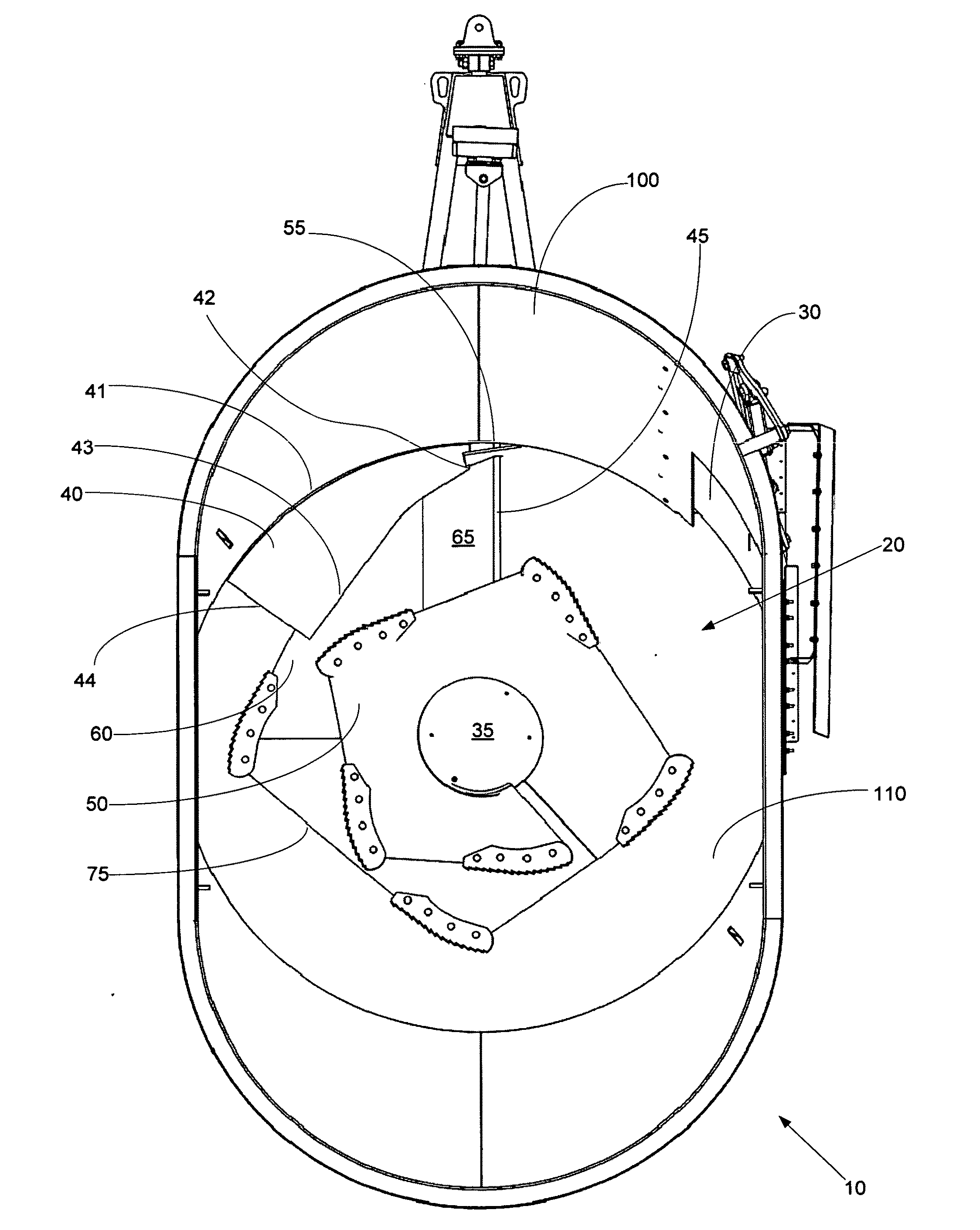
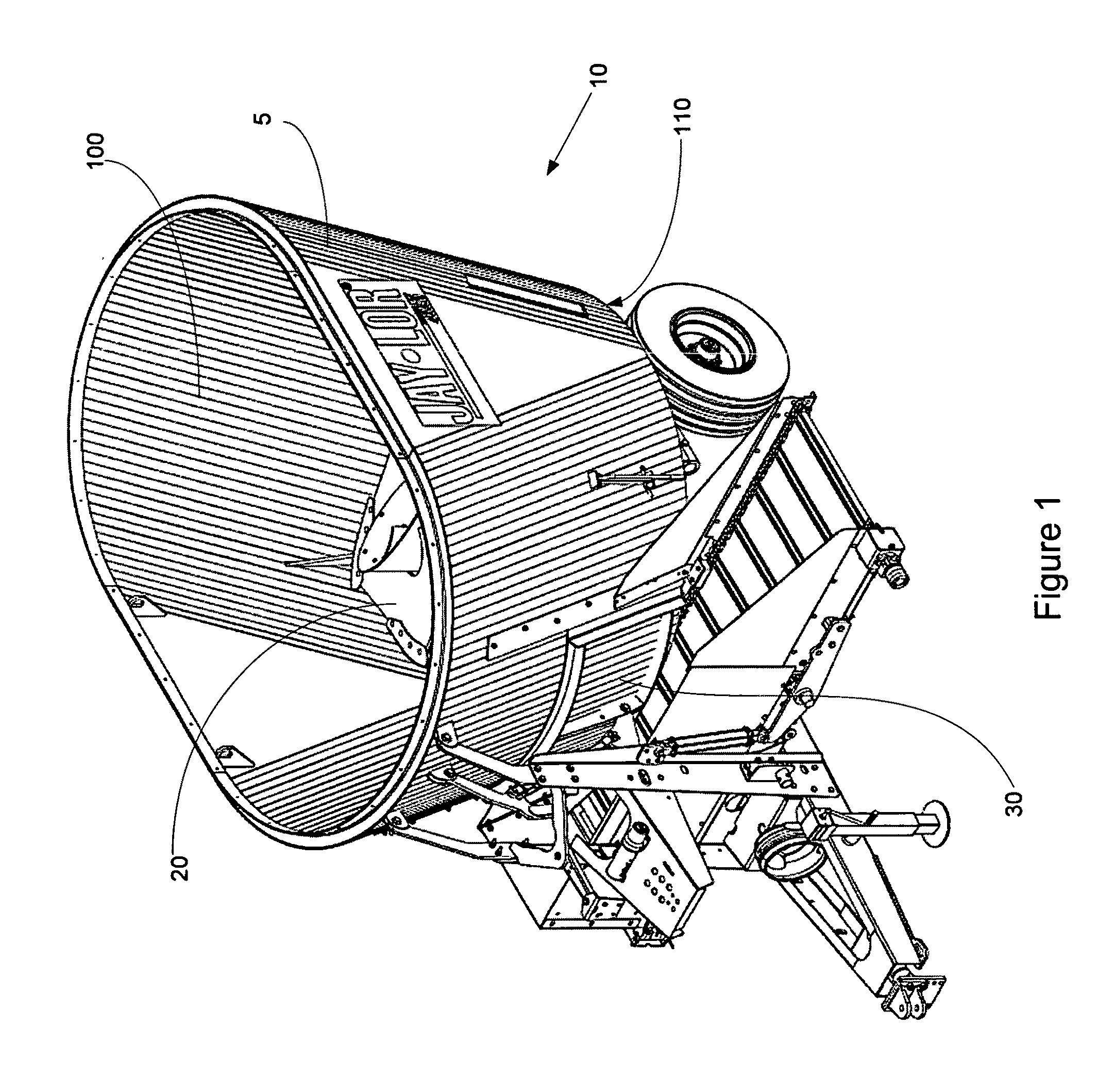
[0084]One embodiment of a vertical mixer having an improved auger is shown with reference to FIG. 1. A vertical mixer 10 has a mixing chamber 5 for receiving bulk material to be mixed. The mixing chamber 5 has an open top for receiving the bulk material, a floor 110, and depending walls 100 defining the mixing chamber 5. A vertical auger 20 is situated in the mixing chamber 5 in a conventional fashion. The mixing chamber 5 includes a door 30 through which mixed bulk material exits the mixing chamber 5 when the door 30 is opened.

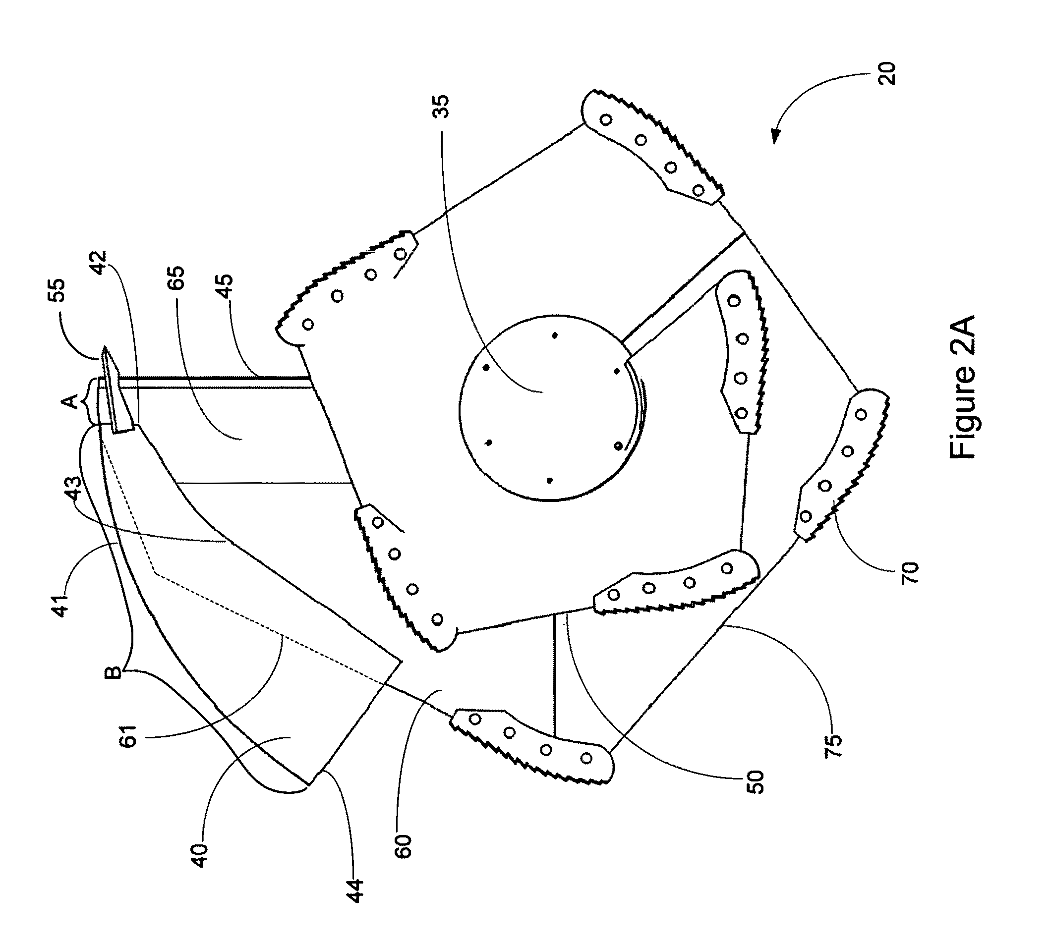
[0085]One embodiment of an example of an improved auger 20 is shown with reference to FIGS. 2A, 2B, 2C and 2D. The improved auger 20 guides bulk material from an outer region of the mixing chamber at least somewhat inwards towards a post 35 of the auger 20. An advantage of the improved auger 20 is that mix quality of the bulk material is improved. Material from an outer region of the mixing chamber is at least somewhat guided inwards towards the post 35 in a ...


PUM


Abstract

A vertical mixer having an improved auger for mixing bulk material is disclosed herein. The vertical mixer comprises a mixing chamber for receiving the bulk material. The mixing chamber being defined by a floor and a peripheral wall and includes a door for allowing exit of mixed bulk material. The vertical auger in the mixing chamber has an auger post and flighting including a bottom flight. The bottom flight has a front leading edge and an outside edge defining an outside footprint of the bottom flight. A slide plate is connected to the bottom flight for guiding bulk material at least inwards towards the auger post. The slide plate comprises a front corner; a bottom edge; and a top edge opposite the bottom edge. The bottom edge has a portion closer to the auger post than the front corner, and a portion extending inward on the bottom flight away from the outside edge of the bottom flight. The slide plate extends from the bottom flight at a shallow angle β relative the floor of the mixing chamber.

Description

FIELD OF INVENTION[0001]The present invention is directed to vertical mixers and more specifically to vertical augers for use with vertical mixers which mix bulk material more effectively.BACKGROUND[0002]Feed for livestock typically includes different ingredients which are required to be mixed together before they are provided to the livestock. For example, hay may be mixed with a variety of feed supplements, such as vitamins, to provide a bulk feed material. Various mixers are known which are designed to mix the bulk feed material to a desired extent. Vertical mixers are disclosed, for instance, in U.S. Pat. No. 5,863,122 (Tamminga) and in U.S. Pat. No. 5,462,354 (Neier).[0003]Many prior art feed mixers include a tub having one or more walls and a floor defining a mixing chamber, with a mixing means, typically one or more augers, vertically positioned in a mixing chamber. In conventional use, the components of the bulk material are cut and mixed together by rotation of the auger. A...

Claims


Application Information

Patent Timeline
Patent Type & Authority Applications(United States)
IPC IPC(8): B01F7/32A23K40/00B01F27/96A23N17/00
CPCA01K5/002A01K5/004B01F7/241B01F2013/108B01F13/004B01F13/1044B01F7/245B01F27/922B01F27/9212B01F33/5023B01F33/8305B01F33/83611
Inventor TAMMINGA, JAKOB
Owner JAY LOR INT INC
Why Eureka
Try Eureka