Objective lens and optical pickup device

a pickup device and optical lens technology, applied in the direction of optical recording heads, instruments, data recording, etc., can solve the problems of difficult manufacturing of optical disks, large thickness of optical disks, and difficulty in thinning apparatuses, so as to reduce the pitch of diffraction gratings

Inactive Publication Date: 2011-03-01
PANASONIC CORP
View PDF10 Cites 0 Cited by
  • Summary
  • Abstract
  • Description
  • Claims
  • Application Information

AI Technical Summary

Benefits of technology

[0013]The invention was made in order to solve the aforesaid problems and an object of the invention is to provide an objective lens and an optical pickup device which can thin the objective lens and a device on which the objective lens is mounted, and which can prevent that the pitch of the diffraction grating at the outer periphery of the objective lens becomes too small in the manufacturing procedure and so it becomes difficult to manufacture the Fresnel lens or which does not require a high-grade fine processing technique in order to minimize the pitch of the diffraction grating.
[0015]According to the aforesaid configuration of the invention, since the outer periphery of the side surface of the objective lens in which the laser light is incident is formed by the refractive lens and the inner periphery thereof is formed by the Fresnel lens, the following two contradictory problems are solved. That is, the first problem is that when both the outer periphery and the inner periphery of the objective lens are entirely formed as the Fresnel lens in order to reduce the maximum size of the objective lens in the optical axis direction, the pitch of the diffraction grating at the outer periphery of the objective lens becomes too small and so it is difficult to manufacture the Fresnel lens or a high-grade fine processing technique is required in order to minimize the pitch of the diffraction grating. The second problem is that when the objective lens is not formed by the Fresnel lens at all, the maximum size of the objective lens in the optical axis direction can not be made small. Thus, according to the embodiment, the objective lens can be made thin to the maximum extent in a manufacturable range. As a result, since the maximum size of the objective lens in the optical axis direction can be made small to the maximum extent in a manufacturable range, the entire size of the apparatus mounting the objective lens can be made thin easily.

Problems solved by technology

However, in the BD driving apparatus (the driving apparatus compliant with a blue ray disk) expected to be spread in the future, since the standard thereof defines to use an objective lens with a numerical aperture of 0.85, the thickness of the center of the objective lens also becomes necessarily larger than that of the CD type and the DVD type, so that there arises a large problem that it is very difficult to thin the apparatus.
Thus, in the optical disk apparatus compliant with a blue ray disk, there is a problem that the entire thickness of the optical disk apparatus must be large by an amount corresponding to the larger thickness of the objective lens.
Thus, although an enlarged diagram of the flat plate Fresnel lens in the optical pickup device of the related art is shown in FIG. 12, this Fresnel lens 111 has a problem that the manufacturing thereof is difficult or a high-grade fine processing technique is required in order to minimize the pitch of the diffraction grating.
According to the current technique, it is almost impossible to manufacture the aforesaid Fresnel lens 111.
That is, the first problem is that when both the outer periphery and the inner periphery of the objective lens are entirely formed as the Fresnel lens in order to reduce the maximum size of the objective lens in the optical axis direction, the pitch of the diffraction grating at the outer periphery of the objective lens becomes too small and so it is difficult to manufacture the Fresnel lens or a high-grade fine processing technique is required in order to minimize the pitch of the diffraction grating.
The second problem is that when the objective lens is not formed by the Fresnel lens at all, the maximum size of the objective lens in the optical axis direction can not be made small.

Method used


Image

  • Objective lens and optical pickup device
  • Objective lens and optical pickup device
  • Objective lens and optical pickup device

Examples


first embodiment

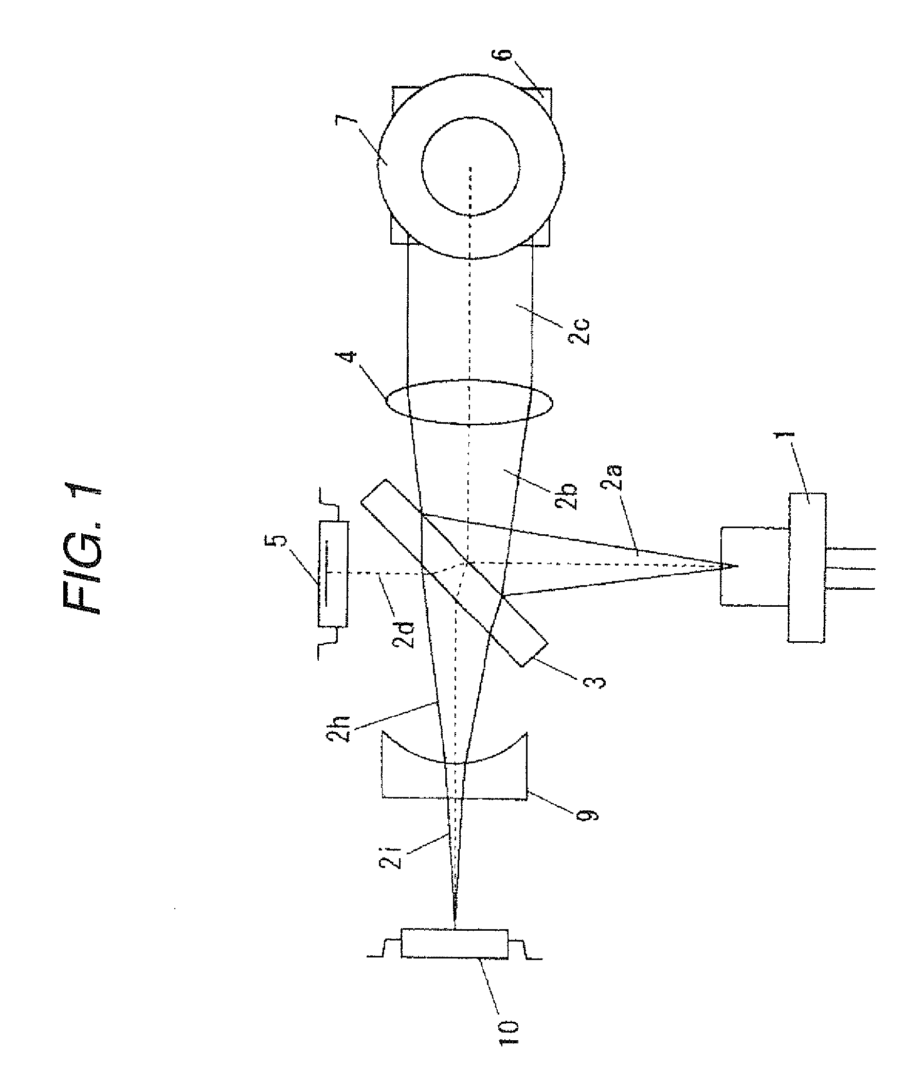
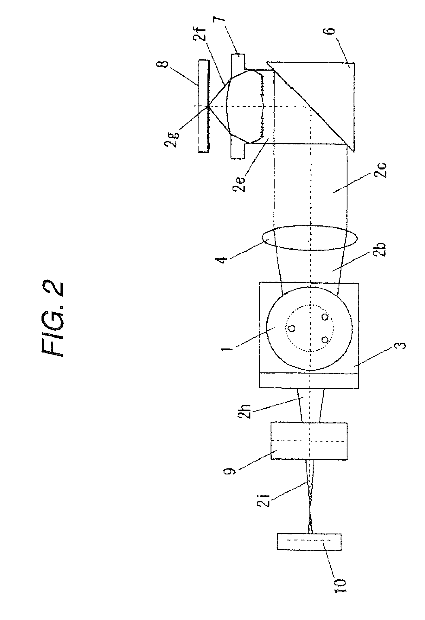
[0029]FIG. 1 is a diagram showing the optical pickup device according to the first embodiment of the invention and is a diagram seen toward the optical axis direction of an objective lens from a recording medium side. FIG. 2 is a diagram showing the optical pickup device according to the first embodiment of the invention and is a diagram of the optical pickup device shown in FIG. 1 seen from the side direction thereof.

[0030]In FIGS. 1 and 2, a laser light ray 2a emitted from a semiconductor laser 1 is reflected by a flat plate beam splitter 3, then incident into a collimator lens 4 as a light ray 2b and formed into a parallel light ray 2c after passing through the collimator lens. A part 2d of the laser light 2a passes through the flat plate beam splitter 3 and is received by a laser emission light monitor sensor 5. The flat plate beam splitter 3 separates an incident light into a reflection light reflected thereby and a transmission light passing therethrough and is mostly designed...


PUM

PropertyMeasurementUnit
thicknessaaaaaaaaaa
thicknessaaaaaaaaaa
thicknessaaaaaaaaaa

Abstract

To provide an objective lens and an optical pickup device which can thin the objective lens and a device on which the objective lens is mounted, and which can prevent that the pitch of the diffraction grating at the outer periphery of the objective lens becomes too small in the manufacturing procedure and so it becomes difficult to manufacture the Fresnel lens or which does not require a high-grade fine processing technique in order to minimize the pitch of the diffraction grating, in an objective lens which condenses a laser light emitted from a light source to irradiate on an optical disk, the outer periphery on the side surface of the objective lens in which the laser light is incident is formed by a refractive lens portion 7a and the inner periphery thereof is formed by a Fresnel lens portion 7b.

Description

BACKGROUND[0001]1. Field of the Invention[0002]The present invention relates to an objective lens and an optical pickup device which perform at least one of the reading and reproduction of information from and into an optical disk or an optical card.[0003]2. Description of the Related Art[0004]FIGS. 8 and 9 are diagrams each showing the optical configuration of an optical pickup device of a related art, in which FIG. 9 is a diagram seen from the side surface of the optical configuration of FIG. 8.[0005]In FIGS. 8 and 9, a laser light ray 102a emitted from a semiconductor laser 101 is reflected by a flat plate beam splitter 103, then incident into a collimator lens 104 as a light ray 102b and formed into a parallel light ray 102c after passing through the collimator lens. A part 102d of the laser light 102a passes through the flat plate beam splitter 103 and is received by a laser emission light monitor sensor 105. The flat plate beam splitter 103 separates an incident light into a r...

Claims


Application Information

Patent Timeline
Patent Type & Authority Patents(United States)
IPC IPC(8): G11B7/12
CPCG11B7/1374
Inventor HORINOUCHI, SHOGO
Owner PANASONIC CORP
Why Eureka
Try Eureka