Electrophoretic displays

a technology of electro-osmosis and display screen, applied in the field of electro-osmosis display, can solve the problems that the electro-osmosis can easily reach the speed of osmosis, and achieve the effect of high field, strong electro-osmotic flow and high for

Active Publication Date: 2015-04-21
ELSTAR DYNAMICS PATENTS BV
View PDF2 Cites 7 Cited by
  • Summary
  • Abstract
  • Description
  • Claims
  • Application Information

AI Technical Summary

Benefits of technology

[0006]To improve the relatively long switching, it is possible to use a slightly different principle, named electro-osmosis, where the particles don't travel through the stationary media, but rather travel together with the media. This creates liquid flow on a microscopic scale, that can transport absorbing particles onto and off a pixel electrode quickly and over relatively large distances. The layout of the electrode will then determine the accuracy and repeatability of the switching behaviour.
[0010]This problem must be overcome by tuning the pixel layout in such a way that vertical vortices are created, which are much larger (e.g. comparable to the pixel diameter) and allow liquid to freely flow onto and off the pixels. The layout of pixels can for example consist of a narrow “pumping area”, which combines a small electrode distance with high field, and which exerts a high force upon the particles and therefore induces strong electro-osmotic flow, and a wider “escape area” next to it, which allows the liquid to leave the pixel again in the opposite direction. Other geometries are possible and may work just as well, as long as the “pumping” feature and “escape” feature are combined in each pixel.

Problems solved by technology

Electro-osmosis, however, can easily reach those speeds using liquid flowing together with the particles, unhindered by particle drag, and only overcoming the friction of the cell walls.

Method used


Image

  • Electrophoretic displays
  • Electrophoretic displays
  • Electrophoretic displays

Examples


Embodiment Construction

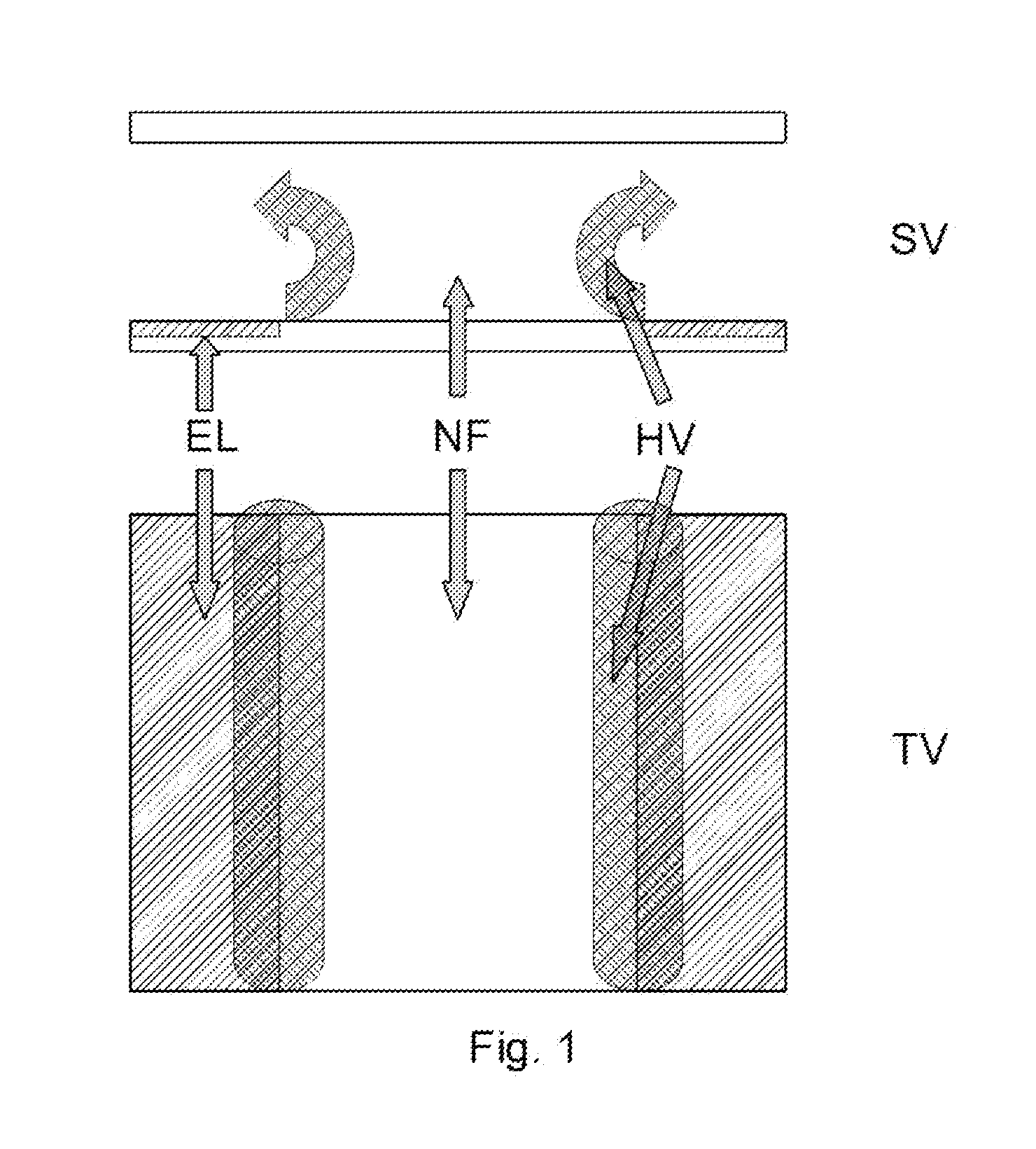
[0017]FIG. 1 shows a side view SV and a top view TV of a pixel in which the liquid flow is limited to the outer edges. The electrode is referred to as El. HV indicates a horizontal vortex and the reference NF means “no flow” of liquid.

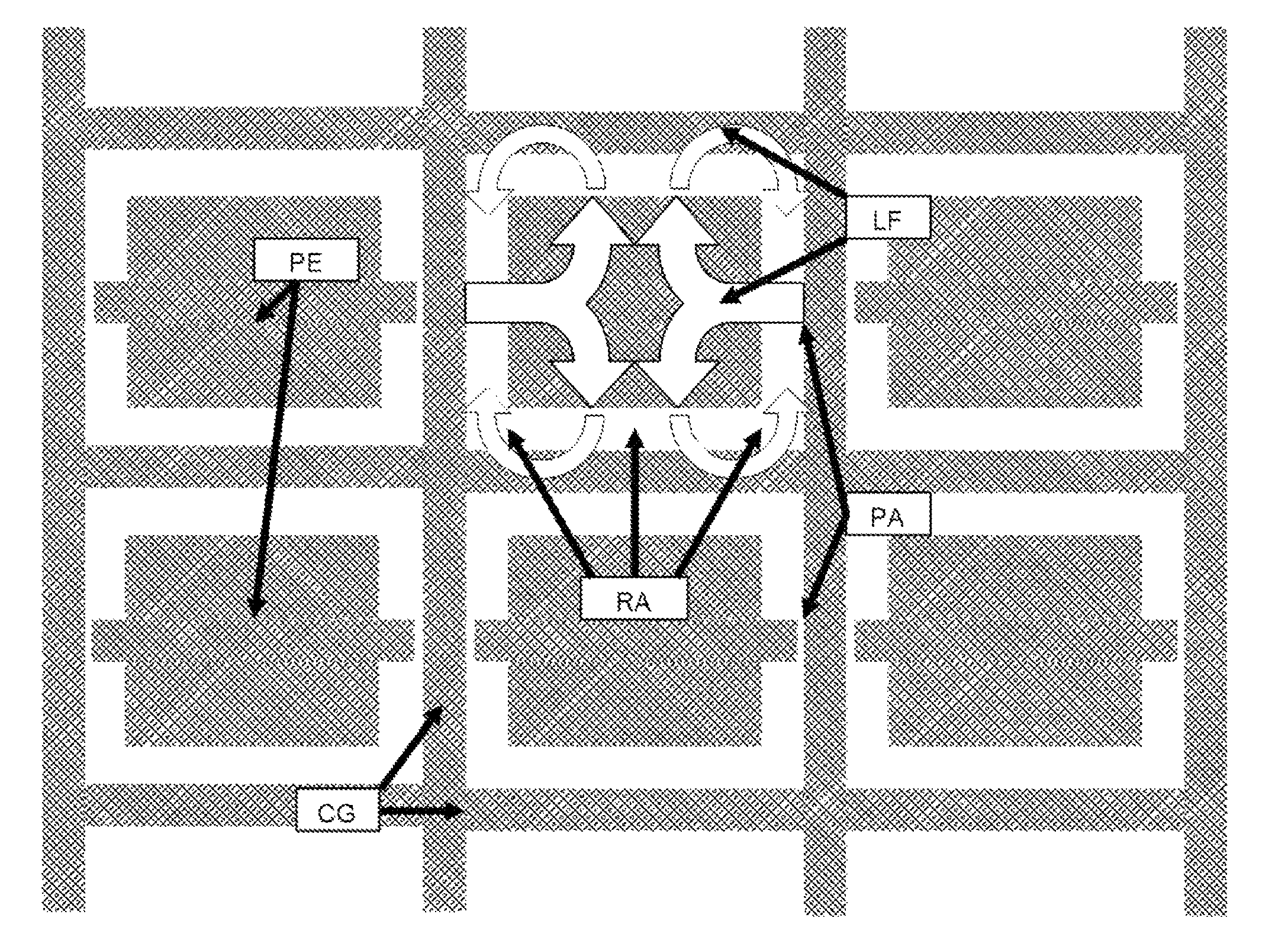
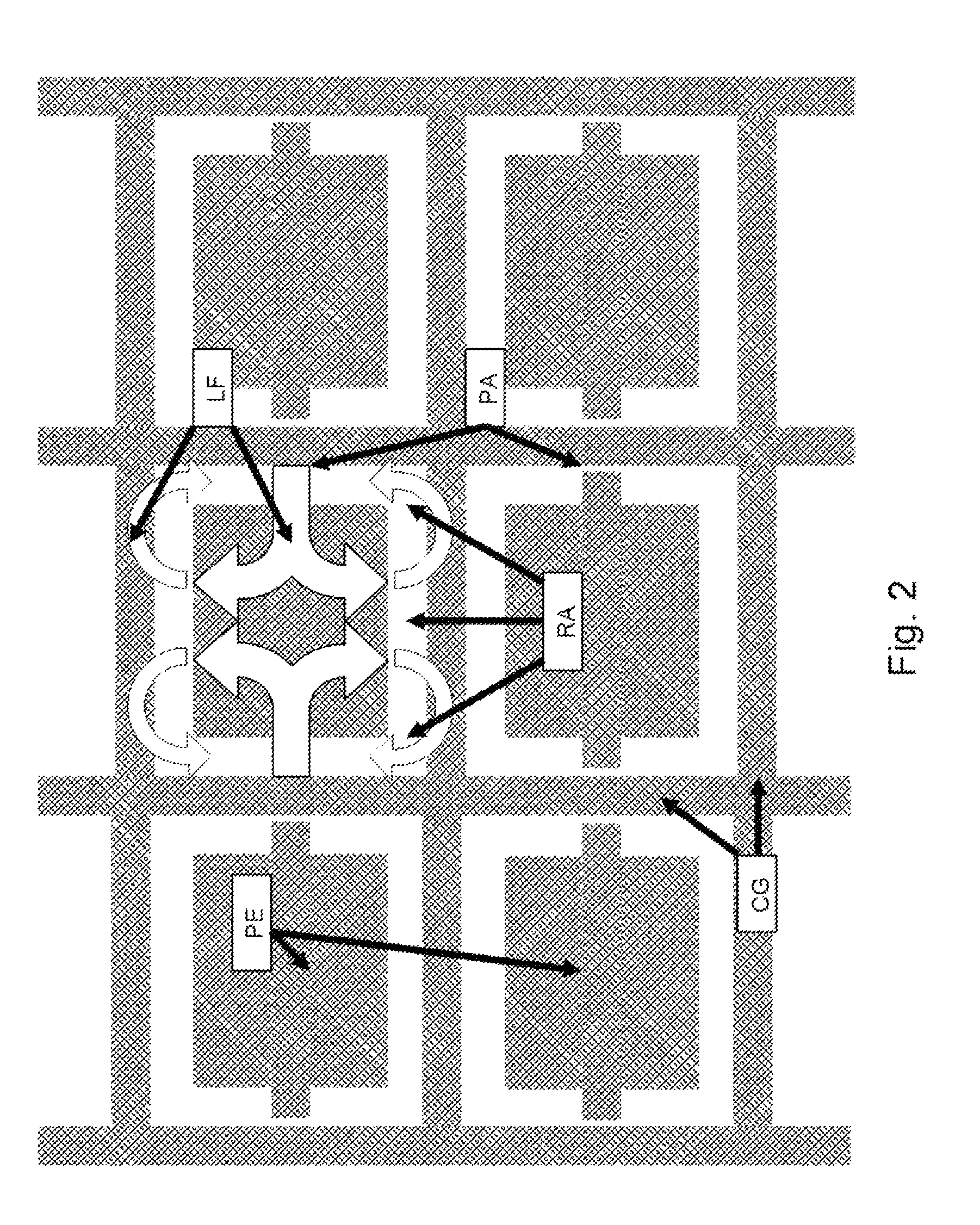
[0018]FIG. 2 shows a top view of pixels in which a fast liquid flow can be induced. The common grid or storage electrode is indicated by CG and the pixel electrode or field electrode by PE. The pumping area is referred to as PA, the release area as RA and the liquid flow is indicated by the arrows LF.

[0019]The electrode pattern is formed by applying a “common grid” or “common lines” (often referred to as “storage electrode”) CG, with pixel electrodes (also called “field electrodes”) PE placed in the “common grid” apertures or between the lines CG (see FIG. 1). Each pixel consists of an area that constitutes the “pump area” PA, which is an area where a small gap between the “common grid” CG creates a high electric field.

[0020]This field exerts a force o...


PUM

PropertyMeasurementUnit
speedaaaaaaaaaa
speedaaaaaaaaaa
sizeaaaaaaaaaa

Abstract

Electrophoretic displays use motion of particles through a fluid to generate images. This invention describes the use of concerted motion of particles together with the solvent to generate optical switching.

Description

FIELD OF THE INVENTION[0001]The invention relates to an electrophoretic display.[0002]This application is the U.S. national phase of International Application No. PCT / EP2011 / 056266 filed 19 Apr. 2011 which designated the U.S. and claims priority to EP 10160579.8 filed Apr. 21, 2010, the entire contents of each of which are hereby incorporated by reference.BACKGROUND OF THE INVENTION[0003]Electrophoretic displays have been the basis of electronic paper for several years now. On the way to improve the switching behaviour and create full color capability, it was suggested to use in-plane switching electrophoretic displays. However, rules for aperture and pixel size dictate that in-plane switching requires particles to travel relatively long distances. Since electrophoresis also requires particles to travel through viscous media, switching can take relatively long.SUMMARY OF THE INVENTION[0004]It is an object of the invention to create fast switching in-plane electrophoretic displays.[0...

Claims


Application Information

Patent Timeline
Patent Type & Authority Patents(United States)
IPC IPC(8): G02B26/00G02F1/167G02F1/1343G02F1/16761
CPCG02F1/167G02F1/134363G02F2001/1676G02F1/16761G02F1/1676G02F2001/1678
Inventor HENZEN, ALEXANDER VICTORGROENEWOLD, JAN
Owner ELSTAR DYNAMICS PATENTS BV
Why Eureka
Try Eureka