Motor

a technology of motors and bearings, applied in the direction of shafts and bearings, dynamo-electric machines, supports/enclosements/casings, etc., can solve the problem of small distortion generation, and achieve the effect of reducing and preventing deformation of bores

Active Publication Date: 2015-04-28
NIDEC CORP
View PDF13 Cites 4 Cited by
  • Summary
  • Abstract
  • Description
  • Claims
  • Application Information

AI Technical Summary

Benefits of technology

[0008]Preferred embodiments of the present invention provide a motor capable of significantly reducing and preventing deformation of a bore of a bearing holder and the resultant distortion of a bearing unit caused by deformation of the bore.

Problems solved by technology

If the center piece undergoes radially inward deformation, it is likely that a small distortion is generated a bearing fixed to the inner circumferential surface of the center piece.

Method used


Image

  • Motor
  • Motor
  • Motor

Examples


first preferred embodiment

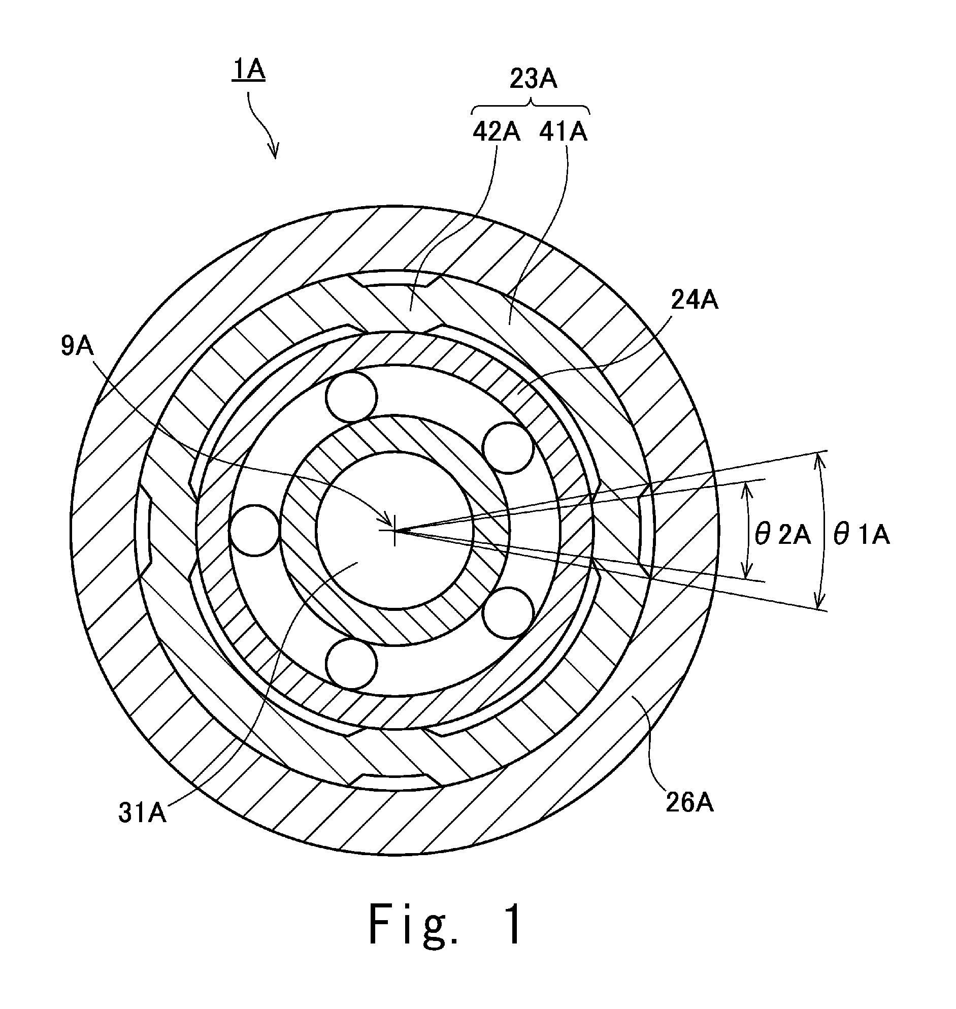
[0034]FIG. 1 is a partial horizontal section view showing a motor 1A according to a first preferred embodiment of the present invention. As shown in FIG. 1, the motor 1A preferably includes a bearing holder 23A, a bearing unit 24A, a surrounding member 26A, and a shaft 31A.

[0035]The bearing holder 23A preferably has a substantially cylindrical shape extending axially along a center axis 9A. The bearing unit 24A is fixed to the radial inner surface of the bearing holder 23A. The surrounding member 26A is fixed to the radial outer surface of the bearing holder 23A. The shaft 31A is rotatably supported by the bearing unit 24A. The motor 1A preferably further includes a magnet (not shown in the drawings). The magnet rotates together with the shaft 31A.

[0036]The bearing holder 23A preferably includes a plurality of holder protrusion portions 41A and a plurality of holder recess portions 42A. The holder recess portions 42A are positioned more radially inward than the holder protrusion por...

second preferred embodiment

[0039]Next, description will be made on a motor according to a second preferred embodiment of the present invention.

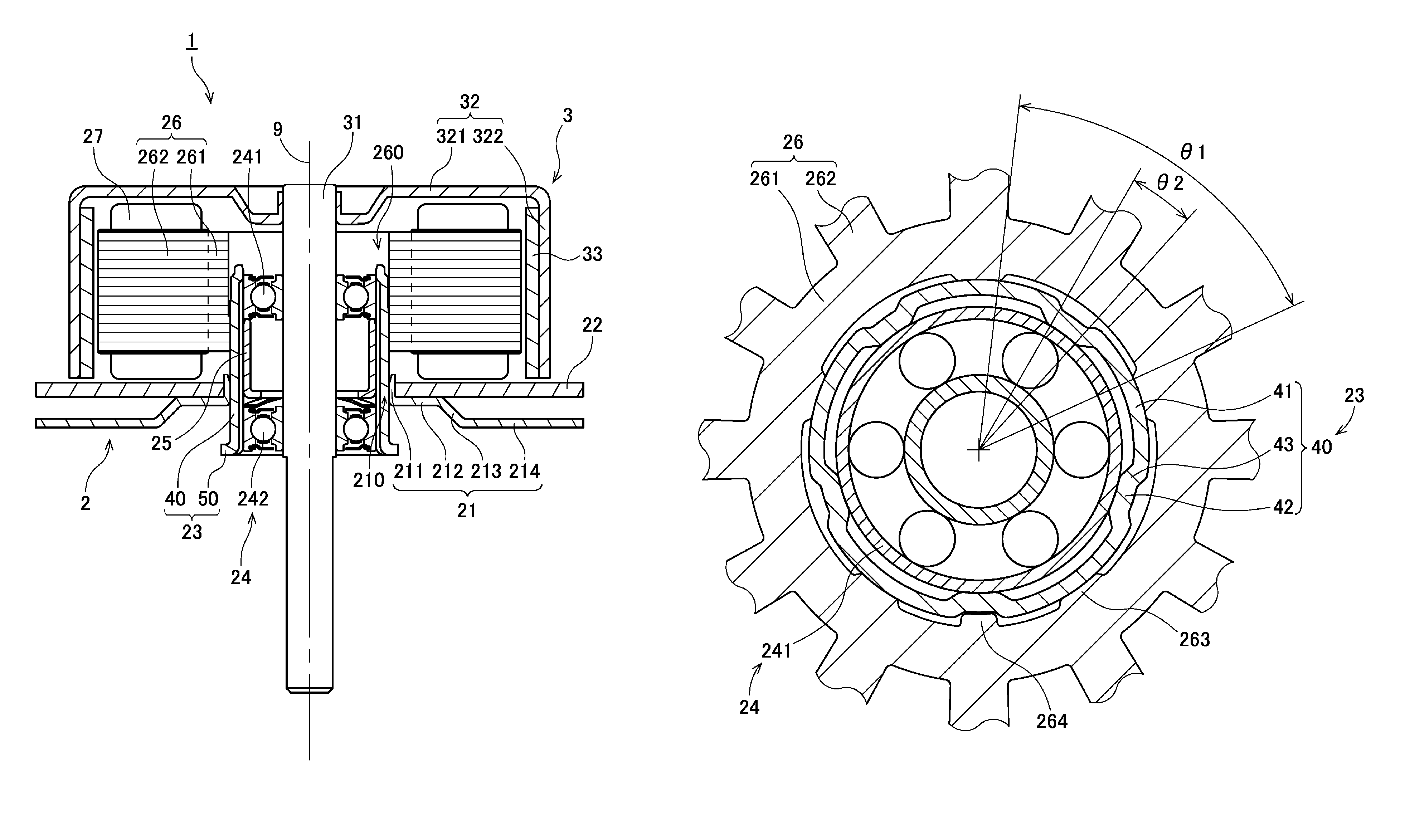
[0040]FIG. 2 is a vertical section view showing a motor 1 according to a second preferred embodiment of the present invention. The motor 1 of the present preferred embodiment is preferably mounted to, e.g., an office automation device such as a printer, a copier, etc., and is used to operate a drive unit such as, for example, a roller or the like. However, the motor of this and other preferred embodiments of the present invention may be used in applications other than the office automation device. For example, the motor of various preferred embodiments of the present invention may be used in a transportation device such as a motor vehicle, a home appliance, a medical device, a disk drive, a blower fan, and so forth.

[0041]As shown in FIG. 2, the motor 1 preferably includes a stationary unit 2 and a rotary unit 3. The stationary unit 2 is kept stationary with respect to ...

third preferred embodiment

[0088]FIG. 10 is a partial horizontal sectional view of a motor 1 according to a third preferred embodiment of the present invention, showing a burring portion 211 and its vicinity. FIG. 11 is a partial vertical sectional view of the motor 1 according to the third preferred embodiment. FIG. 12 is a plan view of the motor 1 according to the third preferred embodiment. FIG. 13 is an enlarged front view showing a fixing portion 219 of the motor 1 according to the third preferred embodiment. The following description will be centered on the points differing from the second preferred embodiment.

[0089]As shown in FIGS. 10 and 11, the burring portion 211 of the attachment plate 21 includes a plurality of caulking sections 215. In the present preferred embodiment, the number of the caulking sections 215 is preferably three, for example. Each of the caulking sections 215 is plastically deformed radially outward beyond the remaining section of the burring portion 211. The lower surface of eac...


PUM


Abstract

A motor includes a bearing holder having a substantially cylindrical shape and a surrounding member fixed to a radial outer surface of the bearing holder. The bearing holder includes a plurality of holder protrusion portions each including a radial outer surface at least partially making contact with the surrounding member and a plurality of holder recess portions positioned radially inward of the plurality of holder protrusion portions. The plurality of holder protrusion portions and the plurality of holder recess portions are alternately arranged along a circumferential direction. A central angle of a portion of an inner circumferential surface of the surrounding member remaining out of contact with each of the plurality of holder protrusion portions is equal to or larger than a central angle of a portion of an outer circumferential surface of a bearing unit.

Description

BACKGROUND OF THE INVENTION[0001]1. Field of the Invention[0002]The present invention relates to a motor.[0003]2. Description of the Related Art[0004]A conventional motor is disclosed in, e.g., Japanese Patent Application Publication No. 2004-229468. The motor disclosed in this publication includes a center piece provided as a support member and a stator core fixed to the center piece (see Paragraph 0020 and FIGS. 1 and 3 of JP 2004-229468. In this motor, a bearing is press-fitted and fixed to the inner circumferential surface of a cylindrical portion of the center piece (see Paragraph 0022 and FIG. 1 of JP 2004-229468).[0005]JP 2004-229468 also discloses an example in which a plurality of projections is formed on the outer circumferential surface of the cylindrical portion of the center piece (see Paragraph 0043 and FIG. 5 of JP 2004-229468). In this example, a plurality of salient portions formed in the stator core makes pressure contact with the outer circumferential surface of t...

Claims


Application Information

Patent Timeline
Patent Type & Authority Patents(United States)
IPC IPC(8): H02K5/16F16C33/02H02K5/173
CPCH02K5/163H02K5/173F16C33/02
Inventor WATANABE, YUJI
Owner NIDEC CORP
Why Eureka
Try Eureka